The RevPi MIO module has various connections. Here you can find out what they are and what you can use them for.
|
Position |
Connection/Signal Display |
|---|---|
|
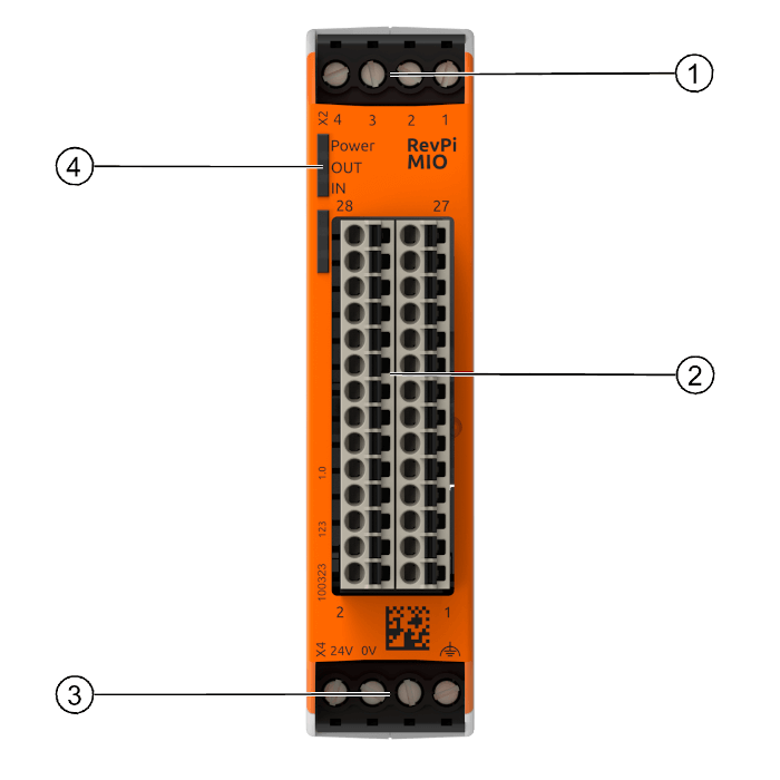
1 |
Digital Inputs and Outputs (GPIO Interface) The four GPIO signals refer to the common system ground. For example you can connect the ground for the digital inputs and outputs to terminals 25 and 26 on the 28-pin connector, on which the analog inputs and outputs are also located. You will find detailed information under “Digital Inputs and Outputs”. |
|
2 |
Analog Inputs and Outputs and Ground for the Inputs and Outputs The RevPi MIO module has:
Here you can connect actuators and sensors working with analog signals commonly in the industry. Please note the pin assignment. That’s very important because the inputs and outputs can be configured differently. The ground for all inputs and outputs is also on this connector strip. Note: All analog and digital inputs and outputs refer to system GND. |
|
3 |
Power Supply Connection |
|
4 |
Status LEDs The IN LED lights up green as soon as an analog input is used. The OUT LED flashes red if a voltage higher than 10.5 V is set at one or more analog outputs. (Note: this feature is no longer supported from firmware version 1.1). |
|
Position |
Connection |
|---|---|
|
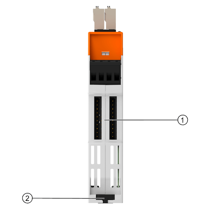
1 |
PiBridge Connections |
|
2 |
Locking Clamp |