How to use status bytes in general is explained in the section “How to Use Status Bytes“.
Status-Byte RevPiLED
The RevPi Core has three LEDs: one qof them indicates the device status, two of them can be used freely. The free LEDs can be controlled by the status byte RevPiLED as follows:
|
LED |
Signal |
Meaning |
|---|---|---|
|
Power |
green |
RevPi Core running |
|
red |
The piControl driver resets, the modules connected to the PiBridge are reinitialized. |
|
|
A1 |
off |
In the “RevPiLED” byte, bits 0 and 1 are set to 0. |
|
green |
In the “RevPiLED” byte, bit 0 is set to 1 and the bit 1 is set to 0. |
|
|
red |
In the “RevPiLED” byte, bit 0 is set to 0 and the bit 1 is set to 1. |
|
|
orange |
In the “RevPiLED” byte, bits 0 and 1 are set to 1. |
|
|
A2 |
off |
In the “RevPiLED” byte, bits 2 and 3 are set to 0. |
|
green |
In the “RevPiLED” byte, bit 2 is set to 1 and bit 3 is set to 0. |
|
|
red |
In the “RevPiLED” byte, bit 2 is set to 0 and bit 3 is set to 1. |
|
|
orange |
In the “RevPiLED” byte, bits 2 and 3 are set to 1. |
Status-Byte RevPiStatus
The byte ’RevPiStatus’ contains the status of the piControl driver. Please note that a distinction is made here between the I/O-Modules (DIO, DI, DO, AIO, MIO) and RevPi Gate modules .
|
Bit |
Meaning |
|---|---|
|
0 |
piControl driver is running |
|
1 |
At least one I/O module is connected that has not been configured by PiCtory. |
|
2 |
At least one I/O module by PiCtory has been configured, but it is not connected. The bit is also set if a RevPi Gate has been configured. |
|
3 |
An I/O module takes up more or less bytes in the process image than specified in the PiCtory configuration. This can happen if the version of the configuration file or the device description files used does not match the firmware in the I/O module. Get an update of PiCtory. |
|
4 |
A RevPi Gate module is connected to the left of the RevPi. |
|
5 |
A RevPi Gate module is connected to the right of RevPi. |
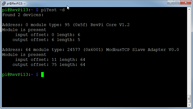
The program piTest -d shows in detail which modules are connected and whether they have been configured in PiCtory or not.
Status-Byte RS485 Count
The status byte “RS485 Count” controls the communication with the I/O modules. This is interesting for you if you want to integrate your own devices into your system.
The RevPi I/O modules (AIO, DIO, DO, DI, MIO) exchange data with the RevPi via a serial line. The data is transmitted electrically according to the RS485 standard.
The piControl driver scans which modules are connected during startup and reset. It then communicates cyclically with the modules in the order in which they are mounted on the DIN rail from left to right next to the RevPi. First, piControl reads the output values for the respective module from the process image and sends them to the I/O module. In response, the RevPi receives the input values and writes them into the process image. This procedure is repeated with the next module and so on in turn.
Although RS485 is insensitive to interference, it can still happen that the data is disturbed during transmission between RevPi and IO module. piControl has an internal error counter for each module. If a transmission error has occurred, the counter is incremented. The maximum value of the counter is 255. As soon as a telegram has been transferred correctly between RevPi to IO module and back, the counter is reset to 0. The first error is ignored, i.e. only if 2 or more errors occur in succession the following error handling will become active.
The value RS485ErrorCnt contains the sum of all errors. The value can therefore be between 0 and 255*n if n I/O modules are connected. At the end of each cycle, the error counter is compared with the two limit values RS485ErrorLimit1 and RS485ErrorLimit2. If it has reached RS485ErrorLimit1, a message is output in kern.log. In the next version of piControl, the default values defined in PiCtory are written to the process image. If the error counter has reached RS485ErrorLimit2, the piBridge communication is stopped.
If one of the values is set to 0, the respective check is deactivated.
RS485ErrorLimit1 is set to 10 and RS485ErrorLimit2 is set to 1000 as default.