This tutorial is valid from the Image Jessie. Unfortunately, it doesn’t apply to Wheezy.
You can use your RevPi Core as Modbus RTU Master. This way you could e. g. connect slaves such as temperature sensors, push-buttons, motion detectors via Modbus RTU and process the data of these slaves in your RevPi Core.
You need:
- RevPi Core
- Slave
- Matching cables with D-Sub 9 connectors
- Adapter
- Internet connection
Requirements:
- A web browser, e.g. Google Chrome or Mozilla Firefox.
- RevPi Core is located in your network.
Let’s go!
- Connect a USB port of the RevPi Core to the adapter.
- Connect the adapter to the slave via the D-Sub 9 socket.
- Specify the address of the slaves and make a note of it. If necessary, you can find information on this in the manufacturer’s operating instructions.
- Find out the device path of your RevPi Core and write it down. Here you learn how it works out.
- Open your web browser.
- Enter the IP address of your RevPi Core in the address bar of your web browser.
The login window appears.
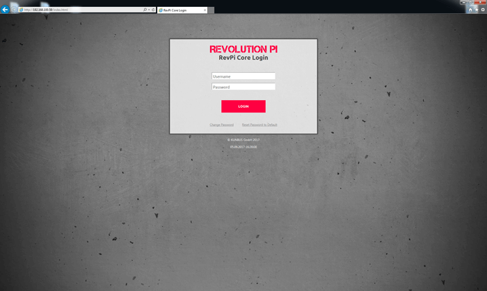
- Log in with the username „admin“.
- Enter the password. You can find it on the sticker on the side of your RevPi Core.
- Click „Login“.
You can now see the current device status of your RevPi Core.
- Click “Services” tab.
- Click “Enabled” in the Enable/Disable Modbus Master line.
- Click the “Save All” button.

Note!: You can also activate the Master function on the command line. Enter the following command: “sudo revpi-config enable pimodbus-master”.
- Click the „Apps“ tab.
- Click the start button behind the entry “PiCtory”.

PiCtory starts.
- Open the folder “Virtual Devices”in the device catalog.
- Select Modbus-RTU Master.
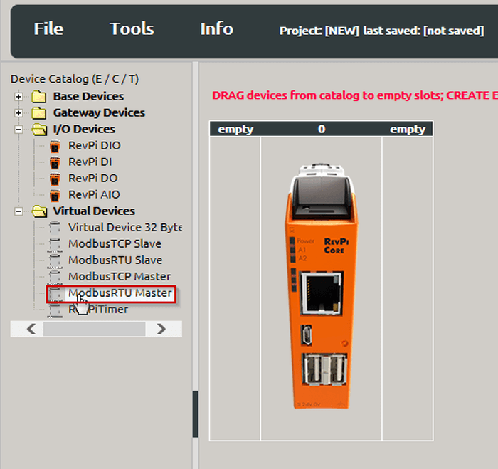
- Hold down the left mouse button and drag the Modbus RTU Master to your RevPi Core.
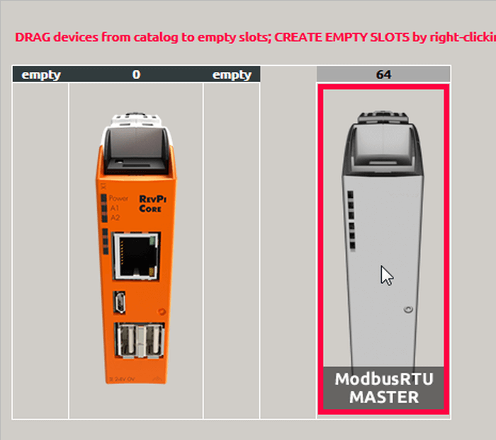
Your Modbus-RTU Master will now appear on the far right of the Configuration Board.
- Select Modbus RTU Master.
- Set the basic settings for your adapters in the “Device Data” window. This entry is optional. If you use a lot of devices and want to process the data later in another program, this input can be very helpful.
- In the “Value Editor” define the settings for the connection:

| Parameter | Description |
| Input | This is where you can configure your inputs. A total of 32 values can be used for each master. A value has a width of 16 bits. |
| Output | This is where you can configure your outputs. A total of 32 values can be used for each master. A value has a width of 16 bits. |
| device_path | The file path to the Linux device file, default: /dev/ttyUSB0
Important! If you are using multiple devices of the same type, the paths to the Linux device files may change when you reboot. This can be prevented by setting udev rules that have e. g. assignments of Linux device file paths to device serial numbers. |
| baud rate | The baud rate determines the speed of the serial connection. default: 19200 |
| parity | Configuration of the parity bit:
None: no parity bit Even: even parity (default) Odd: odd parity |
| data_bits | Number of data bits default: 8 |
| Stop_bits | Number of stop bits default: 1 |
- Right-click on the Modbus RTU Master on the Configuration Board.
- A context menu opens.
- Select the entry “Extended Data”.

An input mask opens.

- This is where you can set the Modbus commands.
We use the first register address 1 for our products. Some manufacturers use 0 as the first register address for their products. Check how the addressing is specified at your slave. If the slave you want to use uses 0 as the first register address, you must add a 1 to the specified value during configuration.
Example: The documentation for your slave states a register address 30053. The addresses start at 0 according to the documentation. You use address 30054 for this register when configuring a Modbus command.
| Parameter | Description |
| Slave Addr. | Slave address
This address is set directly at your slave. For information on how to do this, please refer to the manufacturer’s instruction manual. Important!: If you are using more than one slave, make sure that each slave has its own address. If 2 or more slaves have the same address, communication errors occur. “0” must not be used as slave address. It is reserved for Modbus for broadcast. |
| Function Code | Modbus has function codes that allow access to data in a certain way. We use the following function codes:
READ_COILS Read single bits READ_DISCRETE_INPUTS Read single input bit READ_HOLDING_REGISTERS Read whole 16-bit input/output register Read whole input register (16 bits) WRITE_SINGLE_COIL Write single bit WRITE_SINGLE_REGISTER Writing whole register WRITE_MULTIPLE_COILS Write several consecutive bits WRITE_MULTIPLE_REGISTERS Write several consecutive registers |
| Register Address | The Modbus register address or bit address of the data you want to access
You will find information on how the registers of the slave are assigned in the operating instructions of the slave. The register addresses are always valid in conjunction with the respective function code. This means, for example, that a read holding register no. 17 accesses a different value than a read input register no. 17. |
| Quantity of Registers | Number of registers (or bits) that are read/written |
| Action Interval | The interval at which the command is sent (in milliseconds)
Note that very short intervals cannot be adhered to if the system load is too high. The commands are then sent as quickly as the circumstances allow. |
| Device Value | The variable name in the RevPi process image in which the first word or bit of the Modbus command is read or written.
Make sure that the different commands do not overlap. |
Click on “Add Row” to add another command.
Tip!: You can delete commands by setting the checkmark at the beginning of the command and clicking on “Remove Selected Rows”.
- Click on „File>Save“ to save the file.
- Click on “Tools>Reset Driver”. This activates the changes for the adapter.
Do you want to continue using the settings in logiCAD3 or C?
- Click on „File>Export“.
A window opens. You can specify the format of the file and the filename.
You can choose from 2 file formats:
Export 01 creates a file that is suitable for use in logiCAD3.
Export 02 creates an offset list which you can use as basic information for your own C-program.
- Select a format you want to continue working with.
- Specify a file name.
- Click „Ok“.
Tip!: 32 values are not enough for your project? No problem. Just take another master and access the same slave with it. Now you got 64 values.
OMG! An Error!
In the Modbus master there are specified Modbus registers for status reports.
If a communication error occurs, the error code will be written in the Modbus register “Modbus_Master_Status”.
The error remains in this register until the value “1” will be inserted in the modbus register “Master_Status_Reset”, manually.
| Error Code | Definition |
| 0x10 | The configured device has not been found.
Check if the wiring is correct. |
| 0x11 | The configured device does not respond or you are using a register address that is not allowed at the slave (see hint above!).
Check if the configuration is right. |
The Modbus Master can deal with until 32 tasks. For each task there is a register for Status and Status Reset. If an error occurs within a task, the error code “Modbus_Action_Status_[1 … 32] will be written in the Modbus register.
The error remains in this register until the value “1” will be inserted in the modbus register “Action_Status_Reset_[1 … 32]”, manually.
The error codes correspond to the Modbus Exception Codes specified in the Modbus Specification.
Here the most important error codes:
| Fehlercode | Name | Bedeutung |
| 1 | ILLEGAL FUNCTION | The used Function Code is not allowed. Check, if you are using the Right Function Code. |
| 2 | ILLEGAL DATA ADDRESS | The used Modbus Register Address is not valid. The Register is rather write-protected or invalid. Check the Register Address. |
| 3 | ILLEGAL DATA VALUE | At least one part of the data values is invalid. Perhaps you have specified too many registers. Check your values. |
| 11 | RESOURCE TEMPORARILY UNAVAILABLE | |
| 12 | INVALID CRC | A faulty packet was received from the slave. This can occur after the connection has been interrupted, for example. Check your wiring. |
| 13 | INVALID DATA | The slave has answered with an incomplete packet. This can occur after the connection has been interrupted, for example. Check your wiring. |
| 104 | CONNECTION RESET BY PEER | |
| 110 | CONNECTION TIMED OUT | The slave didn’t respond fast enough or not at all. Check your configuration and wiring. |
More to this subject you can find in the specification of the Modbus.