In this example, we want to make a lamp blink every second. For this example, we use a RevPi Core3, a RevPi DIO and a LED. Furthermore, we have a PC on which CODESYS is already installed.
Preparations:
- Connect the LED to any output of your RevPi DIO.
- Connect RevPi Core and RevPi DIO using the PiBridge.
- Make sure you can operate your device (headless or connect mouse, keyboard and monitor).
- Connect the power supply.
Let’s go:
- Open CODESYS.
- Open a new standard project.
-
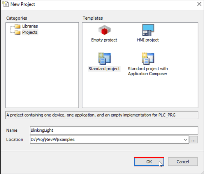
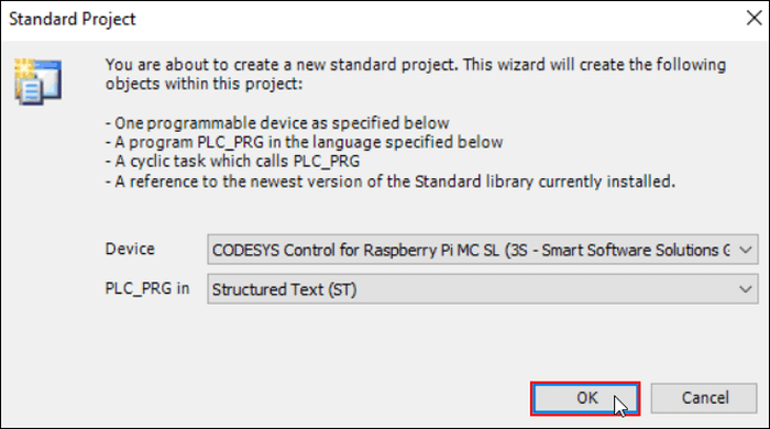
- Select CODESYS Control for Raspberry Pi MC SL as device and one of EN 61131-3 Programming Language for PLC. In this example we use Ladder Logic Diagram (LD).
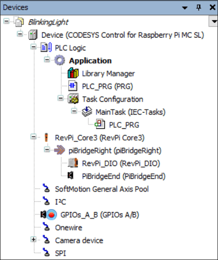
- This shall update the Devices window in the CODESYS editor.
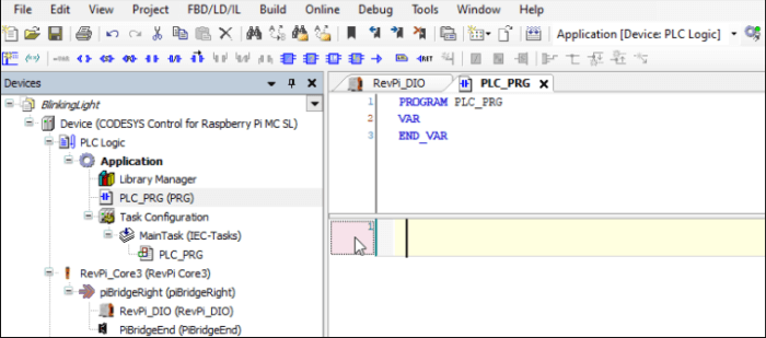
A default POU (Program Organization Unit) PLC_PRG shall be created where the RevPi Controller can be programmed in LD. PLC_PRG is already configured to be called in the Main Task. Therefore no further steps are needed in the task configuration.
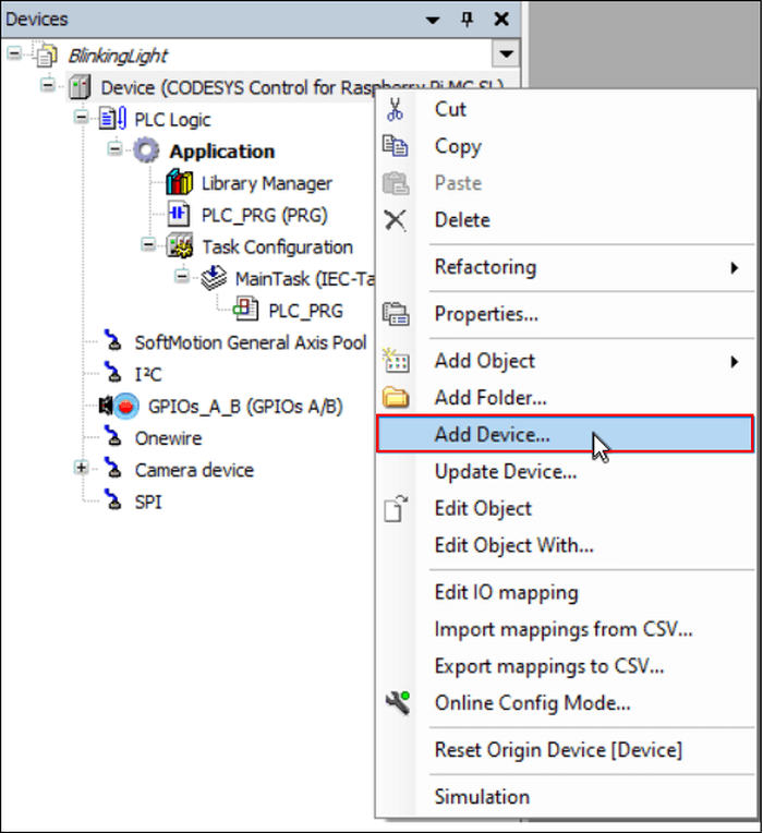
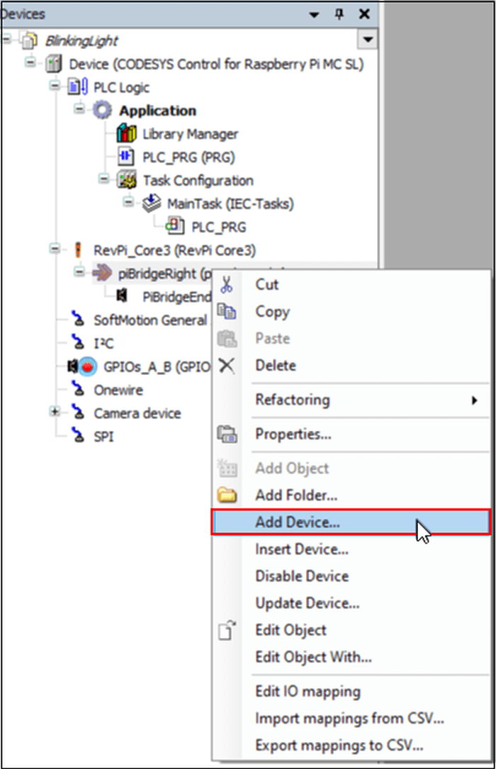
- Now right-click on the root “Device” in the devices window.
- Click on “Add Device”.
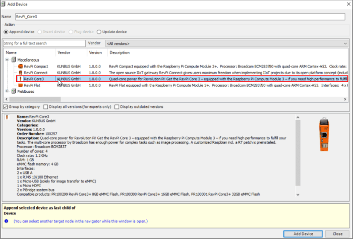
Under Miscellaneous with vendor filter KUNBUS GmbH the KUNBUS based supported CODEYS Controllers will be displayed.
- Select RevPi Core3.
- Click on “Add Device”.
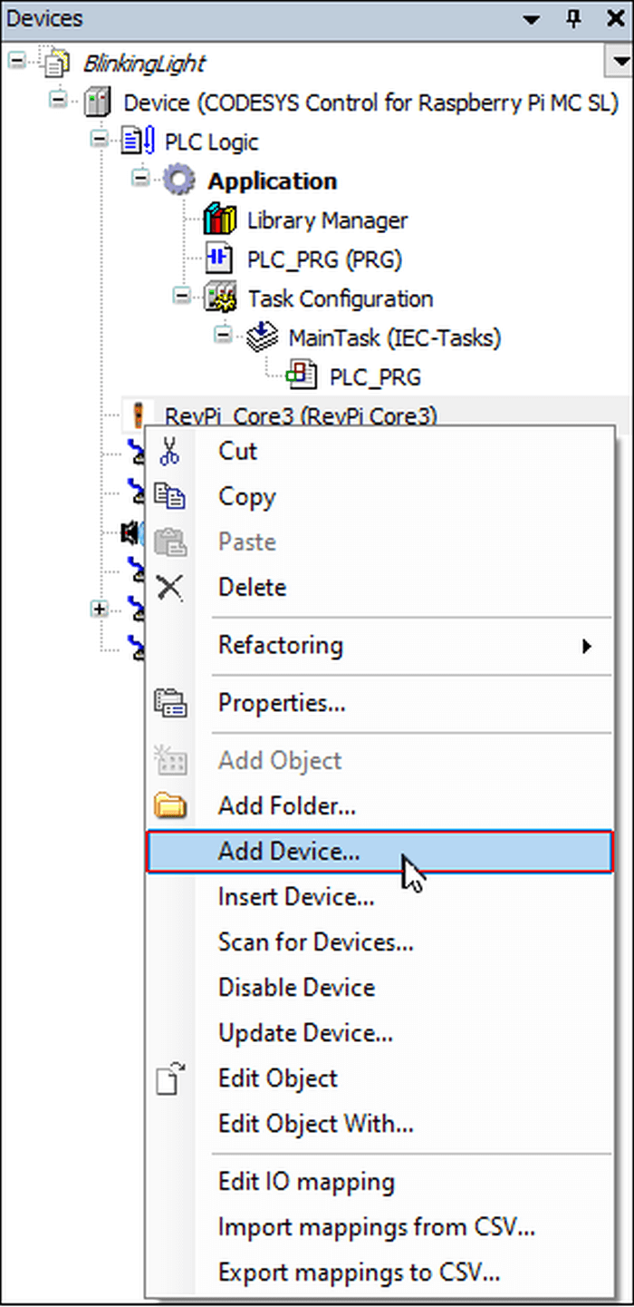
This shall add RevPi Core3 in the CODEYS device tree.
- Right-click on Rev Pi Core3.
- Again select “Add Device”.
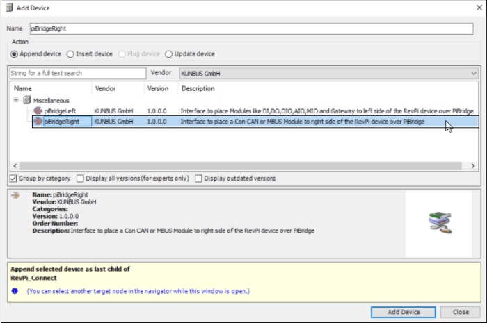
Navigate to the devices listed under “Miscellaneous”.
- Filter by vendor “KUNBUS GmbH”.
- This shall display piBridgeLeft/piBridgeRight device interface option.
In this example, we want to connect a further module on the right side of the RevPi Core3 over piBridge.
- So select “piBridgeRight”.
- Click on “Add Device”.
Notice! If you use a RevPi Connect, you must select “piBridgeLeft”, because a DIO/DO module may only be used on the left side of the RevPi Connect.
The device tree will be updated with piBridgeRight module.
- Select “piBridgeRight” now.
- Click on “Add Device” again.
-
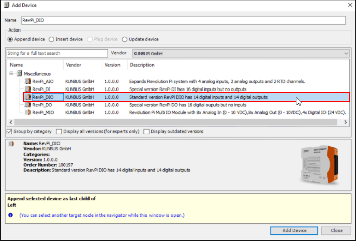
- Navigate to the devices listed under “Miscellaneous”.
- Filter by vendor “KUNBUS GmbH”.
- All modules that can be connected to the right side of the RevPi Core3 are displayed here.
- Select RevPi_DIO.
- Click on “Add Device”.
Now the RevPi_DIO module is added to the device tree.
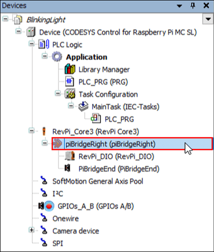
- Double-click on the RevPi_DIO in the device tree.
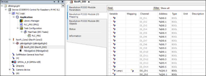
- Navigate to the Revolution Pi DIO Module I/O Mapping tab.
- This is where the used IO”s variables of the corresponding modules can be named. To access them they simply need to be called in a program.
- Write a variable name as “Lamp 1” for DO_Ch1 channel.
-
- Double-click on PLC_PRG in the device tree.
- This will open the program window PLC_PRG where the logic (program) for a blinking lamp connected to the DIO module shall be written in KOP.
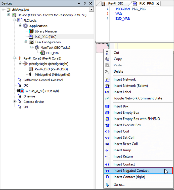
- Right-click on “rung 1”.
- Insert “Negated Contact”.
-
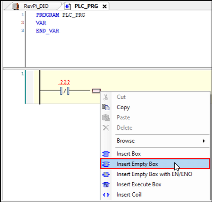
- Right-click on the end of Negated Contact.
- Select “Insert Empty Box”.
-
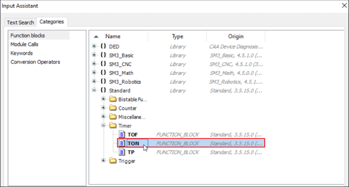
- Select TON in the timer function block from the CODESYS Standard Library.
-
- Click on the name of the function block.
- Press enter.
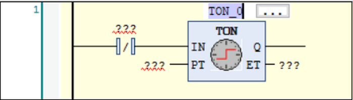
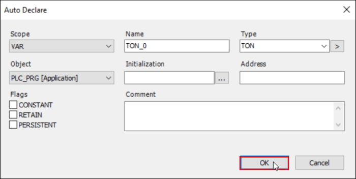
The Auto Declare window pops up. Here you can declare the variable TON as default.
- Click on “OK” for execution.
- Then insert coil on the right side of TON_0.
- Right-click then to add rung 2.
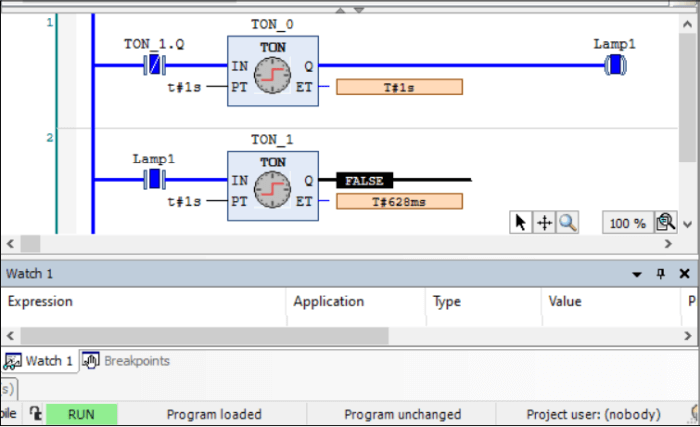
- Complete the logic as shown below.
TON_0 and TON_2 are two TON timers configured with a period of 1s. Lamp1 is the output on the DIO module that we want to blink. The ET field of the timers can be left blank as they are not used.
In rung 1, TON_0 should turn on Lamp1 after 1s. When TON_1.Q is turned on (HIGH) the NC contact TON_1.Q is opened which results in rung 1 evaluating to logic 0 due to which Lamp1 is again off for 1s. So the two rungs help to periodically toggle the output variable Lamp1 between HIGH (1) and LOW (0) states with period 1 s.
- Double-click the root Device in the CODESYS tree.
- Navigate to the Communication Settings tab.
- Click on “Scan network” to find the RevPi Core3. This only works if the RevPi Core3 is physically connected to your network.
- Select “OK” to add the identified device.
RevPi device not found!
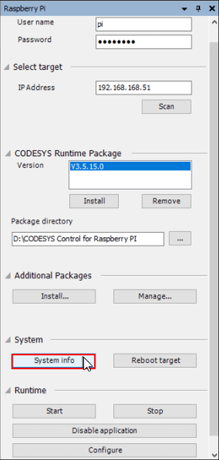
If the previous step was unsuccessful you can investigate further by opening the tab under Tools/Update Raspberry Pi.
- Enter the valid login info and the IP address of your RevPiCore3.
- Select “Scan” to find the devices on the network.
- Click on the “System” tab.
- Click on “System Info”.
- Here you will find the log file of the CODESYS controller under the path /tmp/codesyscontrol.log.
This file can also be viewed by opening a SSH terminal connection with the RevPi device. You can view it with the following Linux command: cat /tmp/codesyscontrol.log .
If no CODESYS runtime is running, you can install one with Install Command from the CODESYS Runtime Package. To find the RevPi device with scan, the CODESYS Control needs to be running and the network IP connection settings need to be valid along with the physical connection.
RevPi device is found!
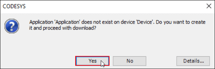
- Now click on the login icon for connecting to the RevPi controller.
- When you download the application for the first time, the following window will be displayed. Select “Yes”.
-
- Click the Start button or press F5. This will start the application.
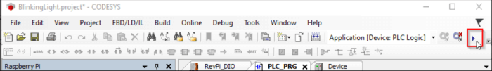
You are now in online mode where you can see the application logic being executed cyclically in task cycle. The lamp connected to the DIO module shall start blinking with a period of 1s.