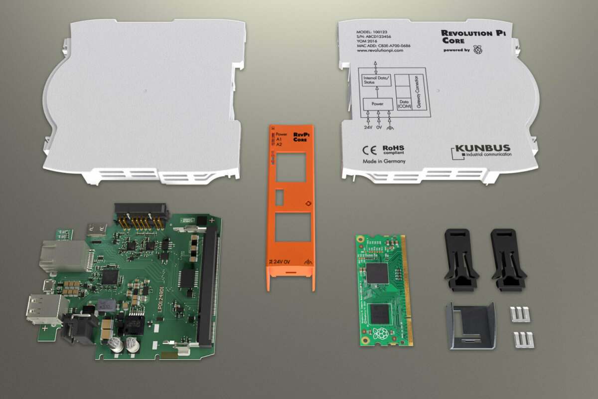
As promised in our last post, today and next week we will take a closer look at the RevPi Core. It’s the CPU of our modular system. The module is widely compatible to a Raspberry Pi Model B+. We do achieve this compatibility by plugging the Raspberry Pi Compute.
For those of you who are in a hurry we’ve put together a table with specifications:
- CPU: BCM2835, 700 MHz
- 4 GByte Flash
- OS: Raspbian / Debian Wheezy with RT-patch of kernel 4.1
- RTC with 24h buffer using long life capacitor
- Driver / API: a central process image is cyclically filled by a driver. Third party software has access to this process image using simple Linux file system commands
- Communication abilities: 2 x USB 2.0 A (each can drive 500 mA), 1 x micro USB, HDMI, Ethernet (RJ45) 10/100 Mbps
- Power supply: min. 10.7 V, max. 28.8 V, max. 10 W *
- Operating temperature: -40 to 55 °C **
- Size (without plugs inserted, H x W x L): 95 mm x 22,5 mm x 110 mm
- ESD protection: 4 kV / 8 kV according to EN61131-2 and IEC 61000-6-2
- Surge / Burst tests: applied according to EN61131-2 and IEC 61000-6-2 using power supply inputs , Ethernet line and IO lines
- EMI tests: according to EN61131-2 and IEC 61000-6-2
Compute Module
The compute module basically consists of two ICs: a Broadcom BCM2835 SoC with 500 Mbyte RAM and a 4 Gbyte eMMC Flash memory. The module is supplied with 1.8 V, 3.3 V and 5 V via the mainboard socket. All IO signals are passed to the mainboard using this single 200 pin wide socket.
Power Supply
The power supply circuit is one of the most important parts of the RevPi Core. In order to get as small heat from power dissipation as possible we are using state-of- the-art high-efficiency DC-DC-converter (efficiency over all is greater than 80%). These converters use 24 VDC input (which is the usual case in industrial applications) to produce all supply voltages needed for the Core.
But our Core module does not only run on the standardized supply range of 20.4 V to 28.8 V but also runs on as little as 10.7 V input voltage**. That means you can even use car batteries or solar panels as power supply. At 24 V input any power loss of up to 10 ms will not influence operation of RevPi Core (drawing full current from both USB ports) and even up to 25 ms without USB load. Input voltage and functional earth is connected to RevPi Core using heavy duty connectors at the bottom side.
A sophisticated protection circuit guarantees continuous operation even under massive electrical or electro-magnetic interference on the input power lines (provided that functional earth is connected properly). Lightning strikes and nearby welding machines have been simulated in our test laboratories but could not impress our RevPi Core modules.
LEDs
RevPi Core has three LEDs each with red or green color. The first LED is reserved for general status report (green = power good, red/red flashing = system error). The other two LEDs are driven by data from the process image (which will be explained later). According to the data found at certain positions these LEDs will change their color or flashing rhythm.
USB and LAN Connectors
The RevPi Core is equipped with two USB-A connectors at the front side which can be used for USB 2.0 client devices. Both connectors can drive up to 500 mA at their 5 V supply pins. Therefore you may plug USB drives or surf sticks directly into these connectors without the need for an active USB hub.
You can connect an USB Host system (usually a PC) with the RevPi Core using the Micro-USB connector in the middle of the front plate. The RevPi Core will then boot in passive eMMC access mode and behave like an USB client memory stick. That way you may flash the module for the first time using an image file from a PC.
A LAN is connected using the RJ45 Ethernet connector. But you may also choose to use a WLAN dongle in one of the USB connectors to connect to your LAN wirelessly.
Just like the Raspberry Pi Model B+ we use a hub/gateway IC LAN9514 from Microchip to get USB lines and Ethernet from the primary USB port of the Broadcom SoC. For best compatibility we’ve tried to get as close as possible to the B+ design.
USB and Ethernet ports are well protected against ESD (electro static discharge) and EMI (electro- magnetic interference).
HDMI
The Broadcom SoC does support high resolution graphic display. RevPi Core is equipped with a Micro-HDMI connector at its top side which may be connected to a monitor and sound system. Together with USB mouse and keyboard this will add up to a complete PC.
RTC
RevPi Core will always know the time even if you have a power failure because it has a real-time clock buffering up to 24 h. Instead of rechargeable batteries we are using a maintenance-free “gold cap”. As soon as RevPi Core is connected to the internet, it will get the correct time from a time server and adjust the RTC setting.
PiBridge
The data highway connecting all RevPi modules is called PiBridge. The modules are physically connected to each other, using a system connector on the top side. Three signal types are exchanged via this connector:
4 pins of the PiBridge are used for automatic module detection during start up phase. After this phase RevPi Core exactly knows which modules are connected and in which physical position they are.
4 pins of the PiBridge are used for rapid data exchange of small data packages using RS485 signals. This channel is also used for module configuration during start up phase. After configuration this channel is used for cyclically exchanging data between RevPi Core and all IO modules connected.
8 pins of the PiBridge are used for rapid data exchange of large amount of data using Ethernet signals. Up to now this channel is only used by our modular gateway modules which may collect up to 512 Byte data cyclically from nearly all relevant fieldbusses.
What`s next?
In part 2 of RevPi Core article we will reveal details about software components, explain the concept of a central process image and discuss how data can be even cyclically exchanged using the internet.
* RevPi Core can only drive 2 x 500 mA USB 5 V supply using input voltages greater than 11 V. EN61131 demands a minimum of 10 ms tolerance against power failure which can only be guaranteed with input voltages form 20.4 V to 28.8 V. At 12 V input voltage this time decreases drastically, especially when driving loads by USB ports.
** Not having heavy USB loads and providing a free heat emission of the housing we have operated RevPi Core up to 65 °C at 24 V input supply voltage without any problems. We can’t guarantee cold start of a cooled down system at ambient temperatures less than -30 °C using 24 V power supply voltage.