In my previous articles, I laid a good foundation for working with the RevPi. Now I would like to focus more on a practical application. Since I want to continue working in C++, I will also use the library I already created in one of my previous articles.
The Revolution Pi in home automation
I thought about using the Revolution Pi for home automation a long time ago. A few months ago, I did some renovations in the house and renewed the electrical installation. All the lines from this part of the house now run together centrally. This allows me to switch lights and, if necessary, sockets flexibly. I would now like to realize this with the RevPi. In addition, I have two LED lights that are too bright for me at night. I would like to dim them. Conveniently, the lights are constructed extremely simply from a few LED board elements and a transformer. The individual parts can be easily separated.
DMX dimmers
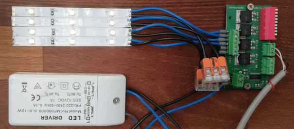
The most practical solution for dimming LEDs with the RevPi is probably the use of DMX. Kunbus offers a DMX gateway for the RevPi and you can find various LED dimmers on the market that can be controlled via DMX. Depending on the range of functions, the dimmers cost between 40 and 100€ for a 4-channel dimmer, e.g. for RGBW. I found a cheap solution (approx. 20€) in the form of a simple circuit board. The board is small enough that you can integrate it into a lamp.
Dimming of LEDs
I would like to say a few words about dimming LED lamps in general, because you have to consider a few things. I have spent some time researching on the internet and thinking about this topic myself and I would like to share the state of my knowledge. In order not to overload this article with too much theory, I put the information in a separate article.
The DMX protocol
DMX is a very simple protocol. There is one master in each string and up to 512 addresses that can be accessed. Theoretically, each of the addresses can be a slave. However, a slave often occupies several addresses. Slaves are pure receivers and the received data is not acknowledged in any way. This makes the protocol very clear.
DMX is based on RS485. The master cyclically sends out one byte per address. Each slave can occupy one or more – typically consecutive – addresses. The address(es) are set on the slave unit. The data is simply sent in sequence after a preamble. The meaning of the data content is not defined by the DMX specification, nor does the DMX master know anything about it. Furthermore, the master has no knowledge about the addressing of the slaves.
For a single-color dimmer, one byte is usually sufficient, but for moving lights, for example, which are often used in event technology, considerably more is required. In this case, axis positions (usually 2 bytes each), the color wheel, the shutter, the gobo wheel, etc. must be addressed. For this purpose, each slave is manually assigned a start address. The slave then picks up the necessary data from the start address. For example, 4 addresses are needed for an RGBW dimmer like the one I use.
Test setup and configuration
Somewhere I still had a few short pieces of LED strips lying around. I also had a 12V power supply in my inventory. Add to that a DMX gateway and the first test setup was ready.
Setting up the Gateway
First I had to find out how the terminal on the DMX module is wired. The tutorial is currently not mentioning this. The DMX gateway’s operating instructions help.

After a little test to see if my soldering attempts on the LED strips were successful, I moved the installation to my wall.

In order to operate the gateway with the RevPi, you have to configure it first. This is done on the one hand with the help of the three rotary switches on the front of the housing and on the other hand in PiCtory. The DMX gateway can be operated in two modes:
- Fixed configuration via the rotary switches on the front of the housing.
- Setting via software → The rotary switches must be set to 0,0,0.
Settings in PiCtory
For now, I decided to use the fixed configuration. The DMX gateway is to function as the master. According to the documentation, any address greater than 512 can be set. This is because a maximum of 512 participants can be addressed or 512 bytes can be transmitted with DMX. All addresses above this are therefore not valid DMX addresses.

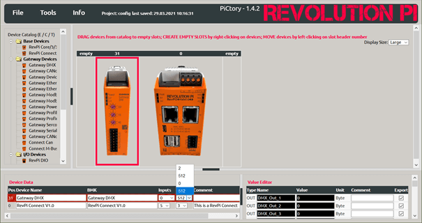
In PiCtory, you must also set whether the fixed configuration or the configuration via software is to be used. There are four options for this under “Outputs”. Only the two “512” are relevant for the master. The upper “512” corresponds to the configuration via software, the lower “512” to the fixed configuration.
The difference can be seen in the Value Editor at the bottom right. In the fixed configuration, only the variables DMX_Out_1, DMX_Out_2, etc. are displayed here. In the software configuration, you will find two configuration bytes Config_1 and Config_2 at the beginning of the list. The exact function of the two bytes you will find in the documentation. These are then designated DMXOut_1, DMXOut_2, etc., i.e. without “_” between “DMX” and “Out”.
If you set the wrong mode in PiCtory, the gateway basically works, only the mapping of the output variables no longer fits. This happened to me in the beginning. In addition, the DMX slave I used started numbering the DMX addresses at 0, contrary to the DMX definition. This led to an additional shift in the mapping and made the confusion complete.
The first test
I set the DMX dimmer to address 0, which actually corresponds to DMX address 1. The dimmer has four channels. Accordingly, addresses 1,2,3,4 are now used by the dimmer.
With piTest -d I first check whether the gateway has been correctly recognized.
Found 2 devices:

Address: 0 module type: 105 (0x69) RevPi Connect V1.0
Module is present
     input offset: 1024 length: 6
    output offset: 1030 length: 5


Address: 31 module type: 100 (0x64) Gateway DMX V1.0
Module is present
     input offset: 0 length: 512
     output offset: 512 length: 512
That looks good!
With
piTest -w <variable name>, <value>
you can write to output variables. The following piTest calls make the installed LED strips turn on properly, as you can see in the picture above.
piTest -w DMXOut_1,255
...
piTest -w DMXOut_4,255
