CODESYS example: BlinkingLight
Introduction
This tutorial explains how to create a simple blinking lamp using CODESYS on the Revolution Pi system. It includes step-by-step instructions and visual aids for better understanding.
Objective
Make an LED lamp blink every second using the RevPi system and CODESYS.
Prerequisites
Hardware Requirements
- RevPi Core 3
- RevPi DIO
- LED
Software Requirements
- CODESYS Development System installed on your PC
System setup
Hardware Setup:
▷ Connect the LED to any output channel of the RevPi DIO module.
▷ Connect RevPi Core and RevPi DIO using the PiBridge.
▷ Ensure the power supply is properly connected.
▷ Operate your RevPi either in headless mode or connect a monitor, mouse, and keyboard to it.
Tipp: For detailed instructions about how to set up your system, refer to the Getting Started guide.
Software Setup:
note: To ensure a compatible system with suitable software, please refer the following links:
Step 1: Create a New Project in CODESYS
▷ Open CODESYS on your PC.
▷ Create a new standard project.
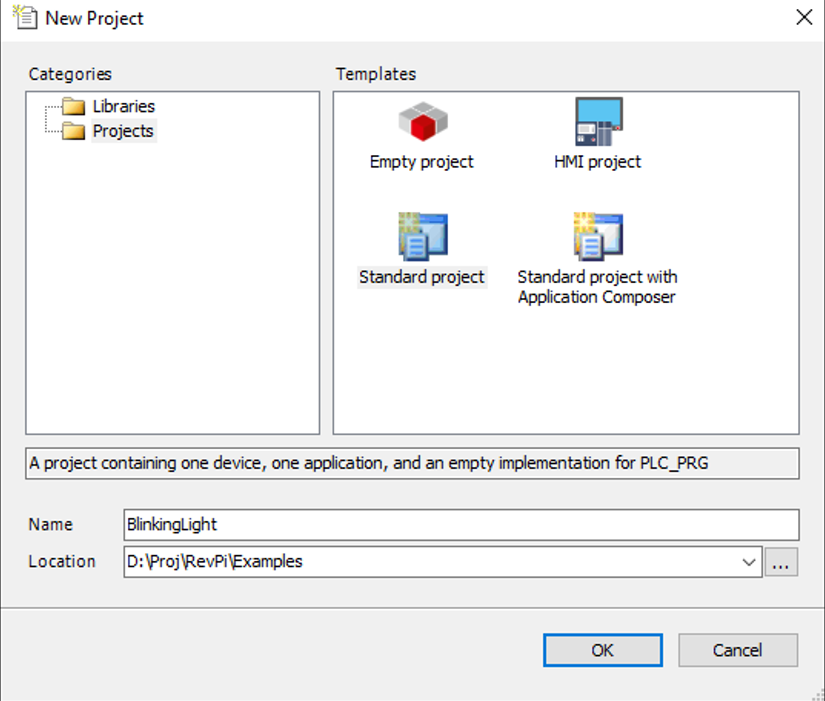
▷ Select CODESYS Control for Linux ARM or ARM64 depending of your image version
▷ Choose one of the EN 61131-3 programming languages for PLC. In this example we use Ladder Logic Diagram (LD).
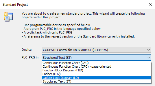
➜ This updates the Devices window in the CODESYS editor as shown in the image below.
Step 2: Configure the Device Tree
A default POU (Program Organization Unit) PLC_PRG shall be created where the RevPi Controller can be programmed in LD. PLC_PRG is already configured to be called in the MainTask. So no further steps are needed in the Task Configuration.
▷ Now right-click on the root Device in the devices window.
▷ Click on Add Device.
➜ Under Miscellaneous with vendor filter KUNBUS GmbH the KUNBUS based supported CODEYS Controllers will be displayed.
▷ Select RevPi Core3.
▷ Click on Add Device.
➜ This adds RevPi Core3 in the device tree.
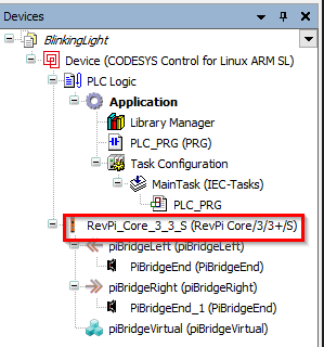
▷ Right-click on RevPi_Core_3_3_S.
▷ Right-click on piBridgeLeft.
note: If you use a RevPi Connect, you must select piBridgeLeft, because a DIO/DO module may only be used on the left side of the RevPi Connect.
▷ Click on Add Device again.
▷ Navigate to the devices listed under Miscellaneous. ➜ All modules that can be connected to the right side of the RevPi Core 3 are displayed here. ▷ Select RevPi_DIO.
▷ Click on Add Device.
➜ The RevPi_DIO module is added to the device tree.

Step 3 Assign Variables for the I/O Module
▷ Double-click on the RevPi_DIO in the device tree.
▷ Navigate to the Revolution Pi DIO Module I/O Mapping tab. The used I/O variables of the corresponding modules can be named here. To access them they simply need to be called in a program.
▷ Assign the variable name wDout to the digital outputs with data type WORD. ➜ Lamp 1 is connected to channel 1 of the digital output of the DIO mod-ule and can be accessed with the first bit using the point operator wDout.0. To access individual bits in a variable with an integer data type, use the following syntax: "variablename"."bitnumber".

Step 4 Write the Logic for the Blinking Lamp
▷ Double-click on PLC_PRG in the device tree. ➜ This will open the program window PLC_PRG where the logic (program) for a blinking lamp connected to the DIO module shall be written in KOP.
▷ Right-click on rung 1.
▷ Select Insert Negated Contact.
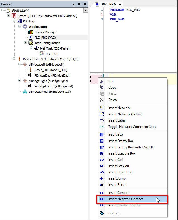
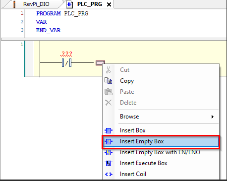
▷ Right-click on the end of Negated Contact.
▷ Select Insert Empty Box.
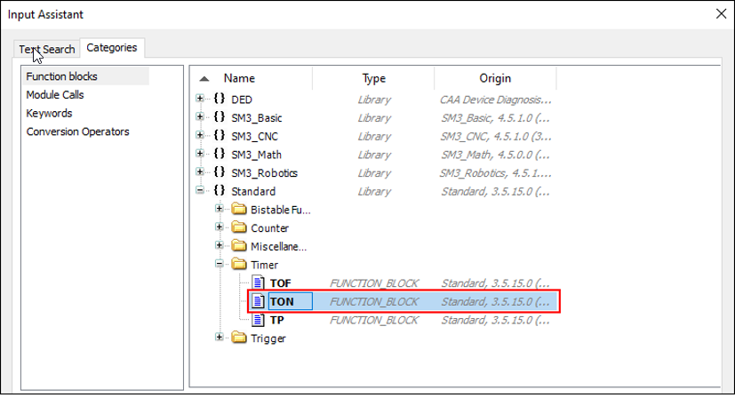
▷ Select TON in the timer function block from the CODESYS Standard Library.
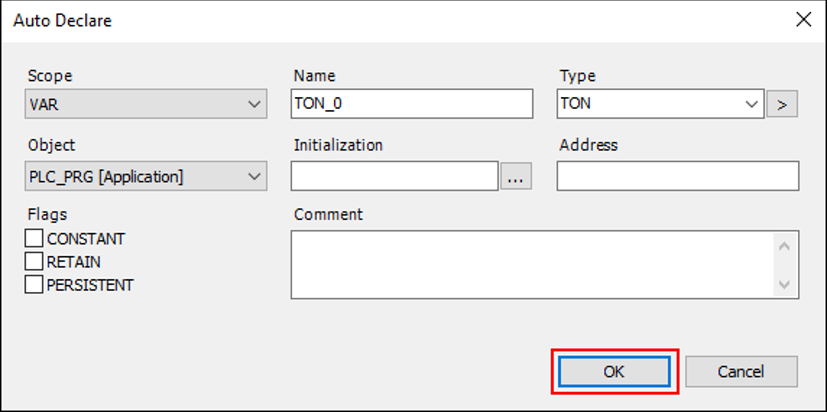
▷ Press enter with TON_0 default name.

➜ The Auto Declare window opens. Here you can declare the variable TON as default.
▷ Click on OK for execution.
▷ Then insert coil on the right side of TON_0.
▷ Right-click then to add network.
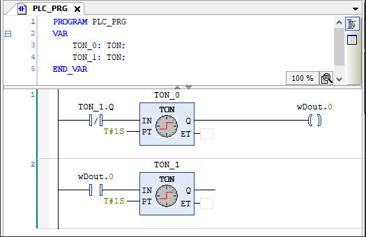
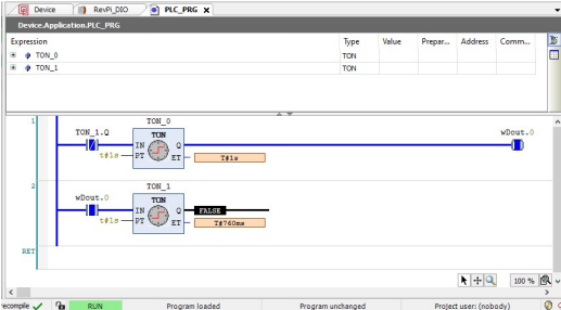
▷ Complete the logic as shown below.
TON_0 and TON_1 are two TON timers configured with a period of 1s. Lamp1 is the output on the DIO module that we want to blink. The ET field of the timers can be left blank as they are not used. In rung 1, TON_0 shall switch on Lamp1 after 1 s. When TON_1.Q is turned on (HIGH) the NC contact TON_1.Q is opened which results in rung 1 evaluating to logic 0 due to which Lamp1 is again off for 1s. So the two rungs help to periodically toggle the output variable Lamp1 between HIGH (1) and LOW (0) states with period 1s.
Step 5: Connect the RevPi in CODESYS
▷ Double-click on the root device in the CODESYS device tree.
▷ Click on the Communication Settings tab.
▷ Click on Scan network to find the RevPi Core3.
This only works if the RevPi Core3 is physically connected to your network and an installed CODESYS Runtime
▷ Select OK to add the identified device.

RevPi Device not Found
If the previous step was unsuccessful you can investigate further by checking the log file. Note: To find the RevPi device with scan, the CODESYS Control needs to be running and the network IP connection settings need to be valid along with the physical connection. ▷ Open the tab under Tools/Update Lim´nux Arm/Arm64.
▷ Enter the valid login info and the IP address of your RevPi Core 3.
▷ Select Scan to find the devices on the network.
▷ Click on the System tab.
▷ Click on "System info".
➜ Here you will find the log file of the CODESYS controller under the path /tmp/codesyscontrol.log.
➜ Here you will find the log file of the CODESYS controller under the path /tmp/codesyscontrol.log
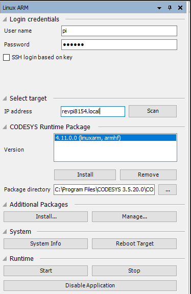
This file can also be viewed by opening a SSH terminal connection with the RevPi device. You can view it with the following Linux command: cat /tmp/codesyscontrol.log .
RevPi Device Found
▷ Now click on the login icon for connecting to the RevPi controller.
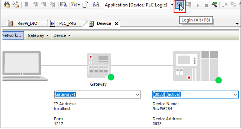
When you download the application for the first time, the following window will be displayed.
▷ Click on Yes.

Step 6. Run the Application
▷ Click the Start button or press F5. This will start the application.

➜ You are now in online mode where you can see the application logic be-ing executed cyclically in task cycle.
➜ The lamp connected to the DIO module should now flash every second.
Troubleshooting
- If the RevPi is not found, check the following:
- Log file: /tmp/codesyscontrol.log.
- Network connection and IP address.
- If the LED doesn’t blink:
Verify wDout.0 is mapped to the correct DIO channel.
- Ensure the logic in PLC_PRG is correctly implemented.