RevPi & CODESYS
CODESYS is a comprehensive development environment for programming and controlling industrial automation systems. It is based on the IEC 61131-3 standard, which is the international standard for programmable logic controllers (PLCs). With CODESYS, users can create and manage automation projects, configure hardware, and develop control applications using various programming languages such as ladder logic, structured text, and function block diagrams.
Revolution Pi can be seamlessly integrated into CODESYS thanks to our drivers, making it a truly modular and powerful microcontroller for a variety of different automation tasks. Since the CODESYS runtime natively supports many fieldbus and industrial Ethernet protocols like PROFINET, EtherCAT, EtherNet/IP, or CANopen, the RevPi can easily be used as a soft PLC in such networks. With CODESYS WebVisu, user interfaces or visualization screens can be created and displayed on any common browser on PCs, tablets, or smartphones. Therefore, no separate HMI software is required.
System Requirements
CODESYS Software
- CODESYS Development System V 3.5.20.0 or higher
- CODESYS Control Linux ARM 32/64 Bit V4.11.0.0 or higher
RevPi Software
- RevPi Bullseye Image 32/64 bit (04/2024) or higher
- Revolution Pi Library for CODESYS V2.0.0.0 or higher
If you are not sure which version of the RevPi image is installed on your RevPi device, you can retrieve it via the terminal of the RevPi device using the command cat /etc/revpi/image-release .
You can update the RevPi image free of charge using the commands sudo apt-get update and sudo apt-get upgrade .
If an older version than the RevPi Bullseye Image (e.g. Buster or Stretch) is installed, install the latest RevPi image. You can download it free of charge from the Revolution Pi download area.
RevPi Devices
The following RevPi devices are compatible with the mentioned software and can be used with CODESYS:
- RevPi Connect 5
- RevPi Connect 4
- RevPi Connect S/SE
- RevPi Core S/SE
- RevPi Flat S
Licensing
Without a valid license, your CODESYS project runs on the RevPi device in demo mode and ends automatically after a runtime of two hours. The demo mode can be used as often as required. For permanent operation, however, you need a fee-based CODESYS license that is suitable for your project.
Which license you need depends on your project. It is determined by parameters such as the number of inputs and outputs, desired fieldbus, desired additional products and project size. If the project parameters change, you can purchase suitable upgrade licenses.
The following questions will help you find the suitable license for your project:
- Which fieldbus is required and how many instances?
- How many I/O channels do you need?
- Does your project contain self-implemented logic and functions that increase the code size?
- Do you need high performance and stable real-time behavior?
You can find the corresponding metrics in the device dialog of the CODESYS Development System under the tab license metrics.
You can find a detailed guide to licensing on the CODESYS page Application-Based Licenses.
You can purchase the licenses in the CODESYS Store on the page for application-based licenses.
For more information about licensing, refer to the CODESYS Online Help.
Installing Software
Before you can use CODESYS with RevPi devices for your own application, the following installation steps are required.
Installing CODESYS Development System
The CODESYS Software is available in 32- and 64-bit versions. Which version is relevant for you depends on whether the RevPi OS is installed on your RevPi device as a 32-bit or 64-bit version. You can retrieve the bit version from the terminal of the RevPi device using the command getconf LONG_BIT .
▷ Download the CODESYS Development System from the CODESYS Store to your PC.
▷ Install the CODESYS Development System on your PC.
Installing the CODESYS Runtime Package on the CODESYS Development System
▷ Download the CODESYS Control for Linux ARM software package from the CODESYS Store to your PC.
▷ Double-click to open the file.
❯ The dialog box Select installation opens.
▷ Select the desired CODESYS version.
▷ Click on Continue.
▷ Accept the license agreement(s) in the Install packages window.
▷ Click on Continue.
❯❯ The software package is installed and the successful installation is displayed.
Installing the Revolution Pi Library for CODESYS on the CODESYS Development System
▷ Download the software package Revolution Pi Library for CODESYS from the Revolution Pi download area to your PC.
▷ Double-click to open the file.
❯ The dialog box Select installation opens.
▷ Select the desired CODESYS version.
▷ Click on Continue.
▷ Accept the license agreement(s) in the Install packages window and select to continue despite the missing signature(s).
▷ Click on Continue.
❯❯ The software package is installed and the successful installation is displayed.
Installing the CODESYS Runtime System on the RevPi Device
▷ Open the CODESYS Development System.
▷ Click on Tools.
▷ Click on Update Linux ARM64.
▷ Enter the login credentials and the IP address of your RevPi device in the Linux ARM64 window.
▷ Select the desired CODESYS Runtime Package.
▷ Click on Install.
❯❯ The CODESYS Runtime Package is installed on the RevPi device.
Creating a Project
Creating a New Project
▷ Open the CODESYS Development System.
▷ Click on File>New Project....
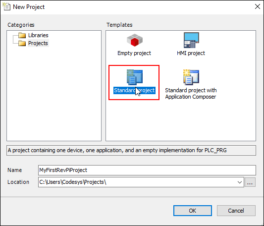
▷ Select Standard project.
▷ Click on OK.
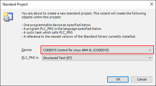
▷ Select **CODESYS Control for Linux ARM SL (CODESYS) **as the device.
▷ Click on OK.
❯ A standard project is created in the project tree.
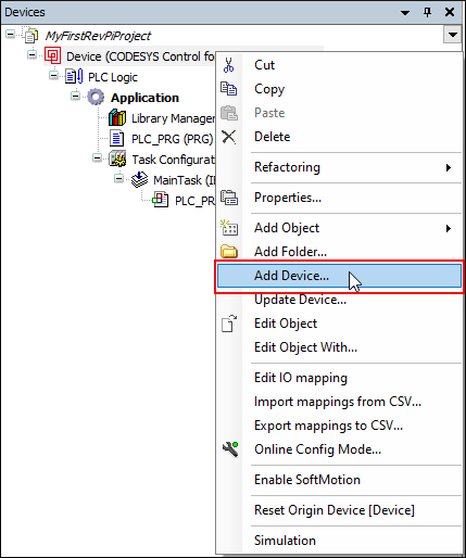
▷ Right-click on Device in the project tree.
▷ Click on Add Device.
▷ Extend the Miscellaneoustree.
▷ Click on the required RevPi base module.
▷ Click on Add Device.
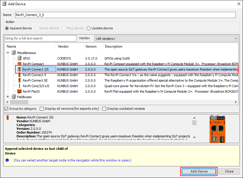
❯ A project with a RevPi base module is created.
Adding RevPi Expansion Module
RevPi expansion modules can be connected on the right or left side, depending on the RevPi base module.
▷ In the project tree, right-click on the piBridgeLeft interface for the left-hand side or piBridgeRight for the right-hand side.
▷ Click on Add Device.
▷ Click on the required RevPi expansion module to be connected to the piBridge interface.
▷ Click on Add Device.
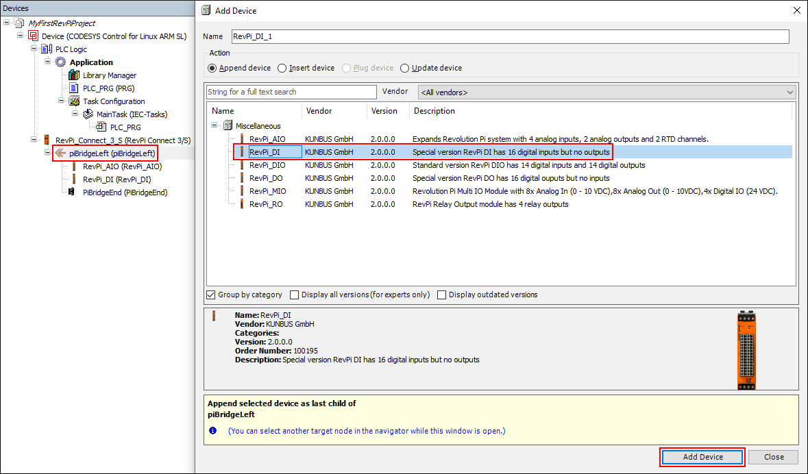
❯ The RevPi expansion module is added to the project.
PiBridgeEnd is a virtual termination of the PiBridge indicating the end of expansion modules on either left or right side of the base module. At this place, a RevPi Gateway can be attached as further end device.
▷ Right-click on PiBridgeEnd in the project tree.
▷ Click on Plug Device.
▷ Select the required RevPi Gateway.
▷ Click on Plug Device.
❯❯ The RevPi Gateway is added to the project.
Loading the CODESYS Project on the RevPi Device
▷ Open the tab for the communication settings by double-clicking on the base device in the project tree.
▷ Select Scan Network.
❯ You will now see the devices that are on your local network.
▷ Select the required device.
▷ Click on OK.
▷ Click on the icon for Loginin the menu bar in the main window.
▷ Confirm the download with Yes.
When you load a CODESYS project onto the RevPi device for the first time, you must set up the user administration once.
▷ Confirm the activation of the user management.
▷ Enter your user-defined login data (user name and password) in the Add Device User window.
▷ Click on OK.
▷ In the Device User **Logon **window, enter the user-defined login data.
▷ Click on OK.
▷ Wait until the download is finished.
▷ Click on the icon for Startin the menu bar in the main window.
❯❯ The application will now be executed and the online mode for debugging will be made available.
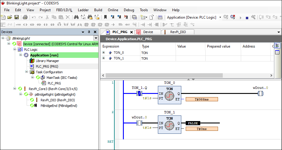
The example BlinkingLight is supposed to make it easier for you to get started working with RevPi and CODESYS.
Adding Connected Devices to CODESYS Project
You can scan devices connected to the RevPi base module with one click and add them to the CODESYS project tree.
Prerequisites
✓ The CODESYS project is loaded on the RevPi device.
✓ The CODESYS project is in online mode.
▷ Right-click on the RevPi device.
▷ Click on Scan for Devices.
❯ This produces a list of all modules connected to the RevPi device.
▷ Click on Copy All Devices to Project.
❯❯ The project tree of the CODESYS project is updated.
▷ Switch to offline mode.
▷ Write the required application and load the new project on your RevPi device.
Backing up and Restoring a CODESYS License
Backing up a License
The CODESYS license can get lost. If the license has not been backed up, it may get lost, for example, after a new image is installed or in the case of a corrupted file system. Save the license for CODESYS outside of your RevPi device so that it is still available to you.
Automatic Backup of the License in CODESYS V3.5 SP13 and Higher
As of CODESYS V3.5 SP13, a license backup file *.WibuCmRaU is automatically saved on the license server and on the computer during the licensing operation. The License Manager can restore the license to the device using this file in case the license files are lost. A manual backup is no longer necessary.
**Saving the License by Explicitly Saving a License Update File ***.WibuCmRaU
For CODESYS versions prior to SP13, the following options are still available for saving licenses that are to be restored at a later date.
▷ Restart the Raspberry Pi device.
▷ Open CODESYS.
▷ Add a device.
▷ Double-click the device.
❯ The device editor opens.
▷ Click on the Files tab.
▷ Switch to the backup folder on the Raspberry Pi device.
▷ Save the file
CMLicenseNew.WibuCmRaU to an external drive.❯ The backup of the license update file to an external drive is created.
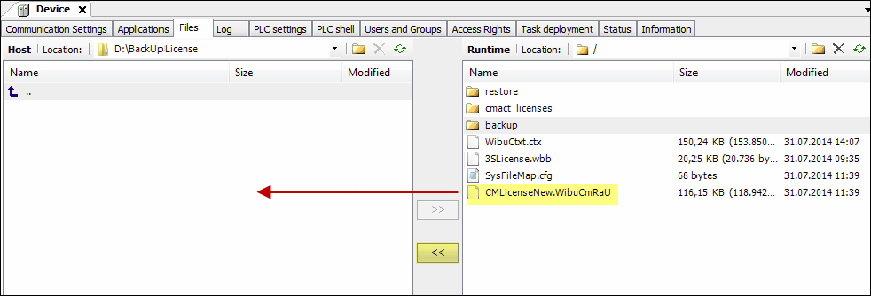
▷ Save the license in the file 3SLicenseInfo.tar.
▷ Proceed as described above for the license update file, but create the 3SLicenseInfo.tar file from the \backup directory on an external drive.
Restoring a License
License activation locks the license to your RevPi device. Activation and reactivation are possible only on the same device.
In the CODESYS Development System V3.5 SP13 and higher, a backed up license is restored by means of the Restore licenses function in the License Manager. This is possible only for licenses that were activated on a soft container.
Restoring the License in the License Manager
▷ Click on Tools.
▷ Select License Manager.
▷ Follow the wizard with the same settings that you used during the licensing operation.
▷ Select Device.
▷ Select Soft container.
▷ After setting up the device, click on the arrow.
▷ Click on Restore license at the bottom left of the License Manager.
❯ The Restore licenses dialog opens.
▷ Specify the ticket ID of the license.
▷ Click on Restore.
❯❯ The license searches for the backup file *.WibuCmRaU first on the local computer and then on the license server. When the license is found, it is reactivated.
For CODESYS versions prior to SP13, the following options for restoring licenses are still available.
Restoring a License from the Explicitly Created License Update FileCMLicenseNew.WibuCmRaU
Requirements: Your development system with CODESYS Development System has Internet access and it is connected to your Raspberry Pi device.
▷ Open CODESYS.
▷ Create a standard project.
▷ Update the device.
The device is the type CODESYS Control for Linux ARM SL.
▷ Open the License Manager.
▷ Follow the instructions of the wizard with the setting Device/Soft container or Dongle/Selection of the target device until you reach the License Manager dialog with the drop-down list for further actions (bottom left).
▷ Select Install licenses.
▷ Select in the following dialog the saved license update file CMLicenseNew.WibuCmRaU .
▷ Click on Finish.
❯❯ The license is restored.
Restoring from the3SLicenseInfo.tar
▷ Copy the previously saved file 3SLicenseInfo.tar into the \\restore directory.
❯❯ The license is restored.
Configuration
On the following pages you will find information about the configuration values of our devices that you need for your settings in CODESYS.
Status Bytes with CODESYS
We use status bytes on the RevPi devices to enter multiple functions or information at a specific location in the process image. In the sections Status Bytes on the RevPi Core and Status Bytes on the RevPi Connect you can find out which status bytes are available on the RevPi devices and how you can use them.
Use of Status Bytes with CODESYS
CODESYS provides an automatic mapping between the variable you use in your application and the status byte of the RevPi device.
▷ Double-click on the RevPi device in the device tree.
❯ The Mapping table opens.
❯ In the column Channel all status bytes of the RevPi device (here RevPi Core) are listed.

▷ In the Variable column, enter a custom name for the status byte you want to use.
❯❯ When loading a project on the RevPi device, the values are mapped automatically.
Mapping of the values in CODESYS
The default values for the configurable status bytes are:
| Status byte | Defaults |
|---|---|
| RS485ErrorLimit1 | 10 |
| RS485ErrorLimit2 | 1000 |
| RevPiLED | FALSE |
If the default values are to be changed, the values must be assigned in the corresponding POU (Program Organization Unit). For more information about POU, refer to the CODESYS Online Help.
Status Bytes on RevPi Core
Status Byte RevPiStatus
The byte RevPiStatus contains the status of the piControl driver. Please note the distinction between RevPi I/O modules and RevPi Gateways.
| Bit | Meaning |
|---|---|
| 0 | piControl driver is running |
| 1 | At least one I/O module is connected that has not been configured by PiCtory. |
| 2 | At least one I/O module by PiCtory has been configured, but it is not connected. The bit is also set if a Gateway has been configured. |
| 3 | An I/O module takes up more or less bytes in the process image than specified in the PiCtory configuration. This can happen if the version of the configuration file or the device description files used does not match the firmware in the I/O module. Get an update of PiCtory. |
| 4 | A RevPi Gateway is connected to the left of the RevPi. |
| 5 | A RevPi Gateway is connected to the right of RevPi. |
Status byte RevPiLED
The free LEDs can be controlled by the status byte RevPiLED as follows:
| Bit | LED | Status information |
|---|---|---|
| 1:0 | A1 | 00 = off 01 = green 10 = red 11 = orange |
| 3:2 | A2 | 00 = off 01 = green 10 = red 11 = orange |
Status bytes RS485ErrorCnt and RS485ErrorLimit
The status byte RS485ErrorCnt controls the communication with the I/O modules. This is interesting for you if you want to integrate your own devices into your system.
The RevPi I/O modules exchange data with the RevPi device via a serial line. The data is transmitted electrically according to the RS485 standard.
The piControl driver scans which modules are connected during startup and reset. It then communicates cyclically with the modules in the order in which they are mounted on the DIN rail from left to right next to the RevPi. First, piControl reads the output values for the respective module from the process image and sends them to the I/O module. In response, the RevPi device receives the input values and writes them into the process image. This procedure is repeated with the next module and so on in turn.
Although RS485 is insensitive to interference, it can still happen that the data is disturbed during transmission between RevPi device and I/O module. piControl has an internal error counter for each module. If a transmission error has occurred, the counter is incremented. The maximum value of the counter is 255. As soon as a telegram has been transferred correctly between RevPi device to I/O module and back, the counter is reset to 0. The first error is ignored, i.e. only if two or more errors occur in succession the following error handling will become active.
The value RS485ErrorCnt contains the sum of all errors. The value can therefore be between 0 and 255*n if n I/O modules are connected. At the end of each cycle, the error counter is compared with the two limit values RS485ErrorLimit1 and RS485ErrorLimit2. If it has reached RS485ErrorLimit1, a message is output in kern.log. In the next version of piControl, the default values defined in PiCtory are written to the process image. If the error counter has reached RS485ErrorLimit2, the piBridge communication is stopped.
If one of the values is set to 0, the respective check is deactivated.
RS485ErrorLimit1 is set to 10 and RS485ErrorLimit2 is set to 1000 as default.
Status Bytes on RevPi Connect
Status Byte RevPiStatus
The byte RevPiStatus contains the status of the piControl driver. Please note the distinction between RevPi I/O modules and RevPi Gateways.
| Bit | Meaning |
|---|---|
| 0 | piControl driver is running |
| 1 | At least one I/O module is connected that has not been configured by PiCtory. |
| 2 | At least one I/O module by PiCtory has been configured, but it is not connected. The bit is also set if a Gateway has been configured. |
| 3 | An I/O module takes up more or less bytes in the process image than specified in the PiCtory configuration. This can happen if the version of the configuration file or the device description files used does not match the firmware in the I/O module. Get an update of PiCtory. |
| 4 | A RevPi Gateway is connected to the left of the RevPi. |
| 5 | A RevPi Gateway is connected to the right of RevPi. |
| 6 | Digital input on terminal X2 |
Status byte RevPiLED
RevPi Connect
Via the byte RevPiLED the free programmable LEDs, the watchdog and the relay can be controlled:
| Bit | Component | Status information |
|---|---|---|
| 1:0 | LED A1 | 00 = off 01 = green 10 = red 11 = orange |
| 3:2 | LED A2 | |
| 5:4 | LED A3 | |
| 6 | Relay | 0 = relay is closed 1 = relay is open |
| 7 | Watchdog | To restart the watchdog timer, the bit must be set once to 0 and once to 1 within 60 seconds. |
Change only the desired bit in the RevPiLED byte. If you want to switch on e.g. LED A3 green, you can write PiTest -w RevPiLED,16. However, this switches off the LEDs A1 and A2 at the same time. You have to read the current value, change the desired bit and then write back the whole byte.
RevPi Connect 4 and RevPi Connect 5
| Bit | Component | Status information |
|---|---|---|
| 2:0 | LED A1 | 000 = off 001 = red 010 = green 100 = blue 011 = orange 110 = cyan 101 = magenta 111 = white |
| 5:3 | LED A2 | |
| 8:6 | LED A3 | |
| 11:9 | LED A4 | |
| 15:12 | LED A5 |
Status bytes RS485ErrorCnt and RS485ErrorLimit
The status byte RS485ErrorCnt controls the communication with the I/O modules. This is interesting for you if you want to integrate your own devices into your system.
The RevPi I/O modules exchange data with the RevPi device via a serial line. The data is transmitted electrically according to the RS485 standard.
The piControl driver scans which modules are connected during startup and reset. It then communicates cyclically with the modules in the order in which they are mounted on the DIN rail from left to right next to the RevPi. First, piControl reads the output values for the respective module from the process image and sends them to the I/O module. In response, the RevPi device receives the input values and writes them into the process image. This procedure is repeated with the next module and so on in turn.
Although RS485 is insensitive to interference, it can still happen that the data is disturbed during transmission between RevPi device and I/O module. piControl has an internal error counter for each module. If a transmission error has occurred, the counter is incremented. The maximum value of the counter is 255. As soon as a telegram has been transferred correctly between RevPi device to I/O module and back, the counter is reset to 0. The first error is ignored, i.e. only if two or more errors occur in succession the following error handling will become active.
The value RS485ErrorCnt contains the sum of all errors. The value can therefore be between 0 and 255*n if n I/O modules are connected. At the end of each cycle, the error counter is compared with the two limit values RS485ErrorLimit1 and RS485ErrorLimit2. If it has reached RS485ErrorLimit1, a message is output in kern.log. In the next version of piControl, the default values defined in PiCtory are written to the process image. If the error counter has reached RS485ErrorLimit2, the piBridge communication is stopped.
If one of the values is set to 0, the respective check is deactivated.
RS485ErrorLimit1 is set to 10 and RS485ErrorLimit2 is set to 1000 as default.
Configuring RevPi DIO, RevPi DO, RevPi DI
CODESYS helps you to configure your RevPi DIO/DI/DO.
▷ Double-click on RevPi DIO/DI/DO in the CODESYS device tree.
▷ Navigate to the first tab Module Parameters.
▷ Set the required values in the Value column.
Configuration Values of the RevPi DIO
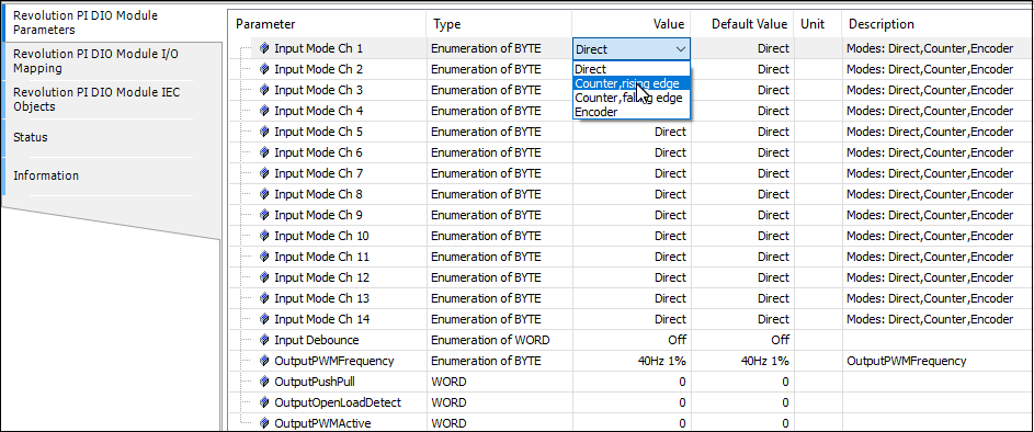
Configuration Values of the RevPi DO

Configuration Values of the RevPi DI
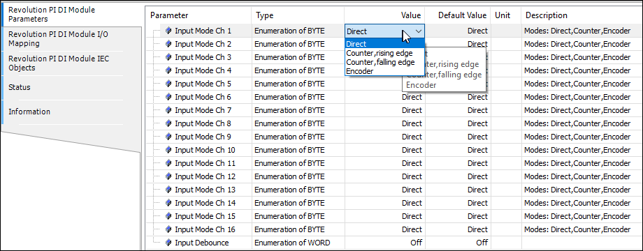
Description of the configurable values of RevPi DIO/DI/DO
In the following you will find a detailed description of the areas Inputs, Outputs, Memory, Counter, Encoder and PWM.
Input
In the input area you can make settings for all parameters your RevPi module receives, e.g. values of a temperature sensor.
| Name | Data Type | Quantity | Offset | RevPi DIO | RevPi DI | RevPi DO | Description |
|---|---|---|---|---|---|---|---|
| Input | WORD | 1 | 0 | X | X | Current values at the inputs. Bits 0 ... 15 (DI) or 0 ... 13 (DIO) show the current values of inputs 1 ... 16 (DI) or 1 ... 14 (DIO). | |
| Output Status | WORD | 1 | 2 | X | X | Bit-coded status of the outputs. Bits 0 ... 15 (DO) or 0 ... 13 (DIO) indicate the current error state of outputs 1 ... 16 (DO) or 1 ... 14 (DIO). 1: Output error (Switch-off due to overtemperature, overload..). 0: No error | |
| Status | WORD | 1 | 4 | X | X | X | Module status NOTICE: Values of bit 0 ... 7 are valid only for RevPi DIO and DI. These bits are not assigned for RevPi DO, since this module has no input ICs. Bit 0: No communication to the input IC Bit 1: UV1* on input 1 ... 8 Bit 2: UV2* on input 1 ... 8 Bit 3: Overtemperature** on input 1 ... 8 Bit 4: UV1* on input 9 ... 16 Bit 5: UV2* on input 9 ... 16 Bit 6: Overtemperature** on input 9 ... 16 Bit 7: Error prompt of the input IC NOTICE: Values of bit 8 ... 16 are valid only for RevPi DIO and DO. For RevPi DI, these bits are not assigned because the module has no output ICs. Bit 8: No communication to the output IC Bit 9: CRC error on output IC Bit 10: Error prompt of the output IC Bit 11 ... 15: undefined |
| Counter | DINT | 16 | 6 | X | X | Current values of the counter or encoder function. | |
| * UV1: The supply voltage for the input ICs has dropped below 7 volts. The alarm is canceled when the value rises above 9 volts. * UV2: The supply voltage for the input ICs has dropped below 14 volts. The alarm is canceled when the value rises above 16,5 volts. Channels 1 … 8 and 9 … 16 have separate bits for UV1 and UV2 because there are two individual ICs in the module that generate this signal. However, the voltage is always identical on both ICs. Therefore, both ICs set their error bit in UV1 or UV2. ** The input ICs signal an overtemperature alarm when 135 °C is exceeded. | |||||||
Output
In the output section you can configure settings for all process values sent by your RevPi module.
| Name | Data Type | Quantity | Offset | RevPi DIO | RevPi DI | RevPi DO | Description |
|---|---|---|---|---|---|---|---|
| Output | WORD | 1 | 70 | X | X | Current values at the outputs.Bits 0 ... 15 (DO) or 0 ... 13 (DIO) indicate the current values of outputs 1 ... 16 (DO) or 1 ... 14 (DIO). | |
| PWM (1 … 16) | USINT | 16 | 72 | X | X | Current PWM values in % for outputs 1 ... 16 (DO) or 1 ... 14 (DIO). These values are only valid if the PWM function is activated for the respective output. |
Memory
In the Memory area you can define how the individual inputs are to be evaluated and how the outputs are to be set.
| Name | Data Type | Quantity | Offset | RevPi DIO | RevPi DI | RevPi DO | Description |
|---|---|---|---|---|---|---|---|
| InputMode | BYTE | 16 | 88 | X | X | Mode selection for each input.Direct: The current value of the input can be retrieved. Counter, rising edge: Rising edges are counted at the input.Counter, falling edge: Falling edges are counted at the input.Encoder: This input is used for encoder function. NOTE: 2 inputs required for encoder function (see section „Encoder“).. | |
| Input Debounce | WORD | 1 | 104 | X | X | This is where a time for the debounce filter is specified for all inputs. This time indicates when a changing state at the input is considered stable. Possible values are Off, 25 µs, 750 µs and 3 ms. | |
| OutputPushPull | WORD | 1 | 106 | X | X | Specifies whether the outputs are operated in push-pull or highside mode. | |
| OutputOpenLoadDetect | WORD | 1 | 108 | X | X | Specifies whether open-load detection is enabled for the outputs. | |
| OutputPWMActive | WORD | 1 | 110 | X | X | Specifies whether PWM is enabled for the outputs. | |
| OutputPWMFrequency | BYTE | 1 | 112 | X | X | This is where, for all outputs that are to be operated in PWM mode, the frequency at which the PWM signal is to be generated is specified. In general: The higher the frequency, the higher the step size in which the clock ratio can be set. |
Counter
You can optionally switch on a counter function for each of the 14 inputs. You can, for example, count the number of times a turnstile or a key has been pressed.
You can find an example of this in our video tutorials.
For each counter, a 32 bit value is then available in the process image.
The current counter value is returned as signed 32 bit value.
Encoder
You can configure all inputs as encoders. The PWM function is helpful if you want to, e.g., control parts of quantities. You can use it to regulate a water supply or dim lights.
You can use a maximum of five encoders.
For each encoder you need two inputs. You must always use the inputs in pairs, e.g.:
Input 1 and 2,
Input 3 and 4
…
Input 13 and 14 (or input 15 and 16 for RevPi DI)
It is important that you always apply the first encoder channel to an odd input. Otherwise your encoder will not be recognized.
The current encoder value is returned as signed 32 bit value for the first channel.
PWM
You can switch on an optional PWM function for each of the 14 outputs.
The PWM function is helpful if you want to, e.g., control parts of quantities. You can use it to regulate a water supply or dim lights.
If PWM is switched on, a whole byte value from 0 to 100 is transmitted instead of one bit per channel, which defines the pulse width at the output as a percentage. By configuration, one of the following PWM frequencies can be set for each module:
| PWM frequency | Resolution of the smallest increment in percent (step size) |
|---|---|
| 40 Hz | 1% |
| 80 Hz | 2% |
| 160 Hz | 4% |
| 200 Hz | 5% |
| 400 Hz | 10% |
The current step size in % is set via an unsigned 8 bit value.
Configuring RevPi AIO
Analog Outputs
CODESYS helps you to configure your RevPi AIO.
▷ Double-click on RevPi AIO in the CODESYS device tree.
▷ Navigate to the first tab Module Parameters.
▷ Click on the corresponding Value cell to set the values.
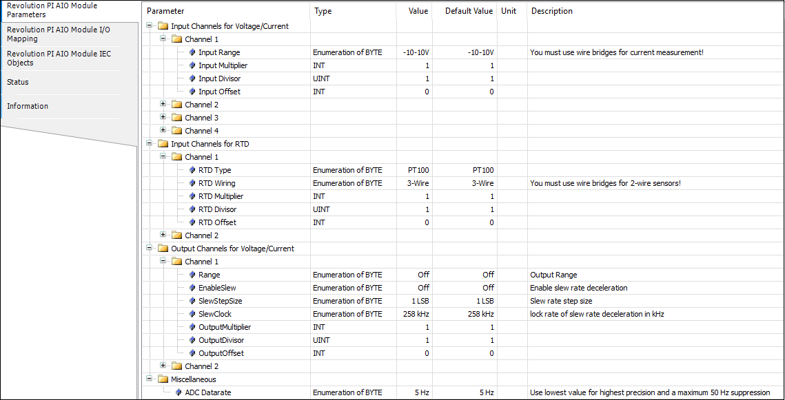
Configurable Values of the Analog Outputs of the RevPi AIO
Your RevPi AIO has two analog outputs. The outputs can emit either voltage or current. You can connect up actuators like e.g. frequency converters for speed control.
For your configuration work it is important that your devices are connected to the correct output pins.
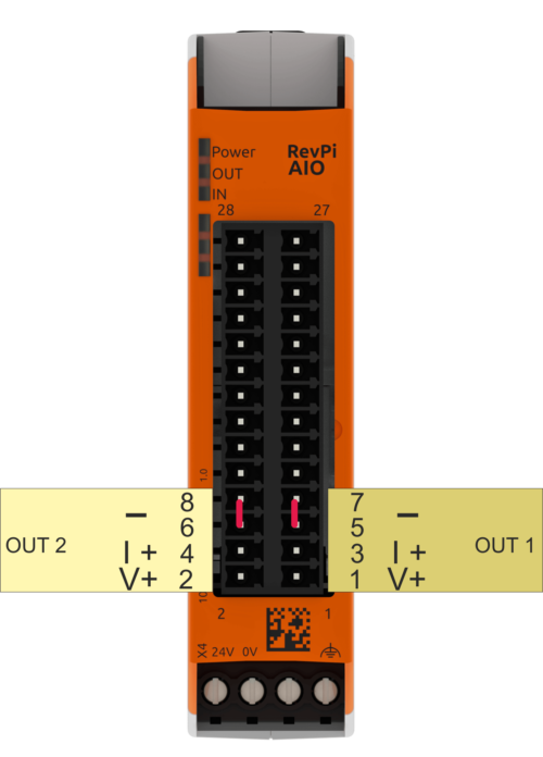
Output 1 (OUT 1)
| Pin | Application |
| 1 | V+ positive output for voltage ranges channel 1 |
| 3 | I+ positive output for current ranges channel 1 |
| 5 | common ground for both output channels 1 and 2 (current and voltage) |
| 7 |
Output 2 (OUT 2)
| Pin | Application |
| 2 | V+ positive output for voltage ranges channel 2 |
| 4 | I+ positive output for current ranges channel 2 |
| 6 | common ground for both output channels 1 and 2 (current and voltage) |
| 8 |
Please note that you only output either current or voltage on one channel, although there are two separate connections. The detailed setting can be found in the following table:
| Variable | Values | Comment |
|---|---|---|
| Output1Range, Output2Range | Set here the value ranges for the current or voltage that the outputs should emit. | |
| Output1EnableSlew, Output2EnableSlew | On = use slew rate Off= do not use slew rate | Here you can specify whether you want to use a slew rate for the respective output. The slew rate controls the rate at which the output voltage or current changes when you set a new value for an output in the process image. |
| Output1SlewStepSize, Output1SlewStepSize | Here you can select the slew rate step size for the respective function. Step size 1 corresponds to the smallest bit value (LSB) from the converter. Together with the clock frequency, the step size determines the slew rate between two analog values. | |
| Output1SlewUpdateFreq, Output1SlewUpdateFreq | Here you can select the step clock frequency for the slew rate of the respective output. Together with the clock frequency, the step size determines the slew rate between two analog values. | |
| Scaling output 1:****Scaling output 2: | Here you can set a scaling for every output channel. It is determined by the three configuration values and calculated from the original value (available in mV or µA) according to the following formula: Y = X*Multiplier/Divisor + Offset |
Scaling
The scaling can be used for the conversion into other units or for a subsequent calibration of an actuator. A 32-bit integer arithmetic is used for calculations in the RevPi AIO module. The results are then sent again as 16-bit values to DAC. Should the result Y exceed the limits of a 16-bit signed value, the fault will be recognized and the value limited. The output values for scaling factor 1 always have to be stored in the process image in the unit mV or µA respectively.
Example:
A frequency converter triggers an electric motor. It has an analog input of 0 to 10 V, whereby 0 V corresponds to a speed of 200 rpm and 10 V a speed of 3000 rpm. To store the speed in rpm in the process image, you have to select the parameters for the output range 0 ... 10 V as follows:
Multiplier = 100, Divisor = 28, Offset = -714
The slew rate settings have the following meaning:
Let's assume you have selected an output range from 0 to 10 V. In the process image there is an output value of 3 V for channel 1. This value is now to change to 8 V. Therefore you write the number 8000 instead of the 3000 mV to the corresponding offset in the process image. In the next PiBridge cycle, the figure is then consigned to the DAC (Digital to Analog Converter) which then generates the analogue voltage for the output. This takes place with a certain delay time of 10… 40 ms depending on the load on the PiBridge (which depends on the configuration). After this delay, the output voltage would jump from 3 V to 8 V very quickly. The slew rate of the voltage is only dependent on the total capacity at the output (which amongst other things is dependent on the connected devices). As a rule, it should amount to a few µs. The slew rate is often not desired because it has an extremely high frequency ratio that can lead to interference radiation and other problems. You can therefore artificially reduce the slew rate. To do so, click on Output?EnableSlew. Now the DAC will, as soon as it has received the new data (8000), increase the output voltage in small steps until 8 V is reached. You should set the amplitude by yourself by going to Output?SlewStepSize. This step size is indicated as a LSB (Last Significant Bit). As our converter works with a 16 bit resolution in every output range, the step size of the lowest valued bit (LSB) measures, in the 0 ... 10V range, 10V/2^16 = 0.15 mV (or respectively 0.30 µA in the 4 ... 20 mA range). The number of minute steps that the DAC needs depends therefore only on the voltage jump: In our example, it is, for a step size of 1, therefore 5000 mV / 0.15 mV = 33,333 steps. The time in which these steps are performed is determined by the clock speed by which the steps are integrated into the signal. They can be set by yourselves by means of the Output?SlewClock parameter. When the clock speed is set at 3.3 kHz, the edge needs from 5 V, therefore 33,333* 1/3300 s = 10 s. When set at 258 kHz, it is therefore 130 ms. The slew rate is, for a 3.3 kHz clock speed, therefore 0.5 V/s or 38 V/s respectively when the clock speed is 258 kHz. You can drastically increase the slew rate with larger step sizes. However, the signal will also skip so that it will receive significantly greater share of high frequency signals.
Should an error occur, you will receive error messages in the input values of the process image named InputStatus_1-4. The values have the following meanings:
| Bit Position | Status Message |
|---|---|
| 0 (LSB) | Temperature error of the output chip. The output chip is overheated as a result of overloading (short circuit). |
| 1 | Open Load error of the current output. In the Current Output operating mode, the connected circuit is highly resistive because, for example, the supply has been interrupted. |
| 2 | Internal CRC error of the output chip. The error points to a hardware defect or serious external interference signals. |
| 3 | Range Error: The output value in the process image is below the configured output range. |
| 4 | Reserved for internal purposes |
| 5 | The supply voltage for the module is less than 10.2 V. The outputs have been shut down. |
| 6 | The supply voltage for the module is greater than 28.8 V.The outputs have been shut down. |
| 7 (MSB) | Timeout in the connection to RevPi Core/Connect (e.g. due to a malfunction of the PiBridge or if the driver program PiControl is no longer running correctly on the RevPi Core/Connect.) The outputs have been shut down. |
Analog Inputs
CODESYS helps you to configure your RevPi AIO.
▷ Double-click on RevPi AIO in the CODESYS device tree.
▷ Navigate to the first tab Module Parameters.
▷ Click on the corresponding Value cell to set the values.
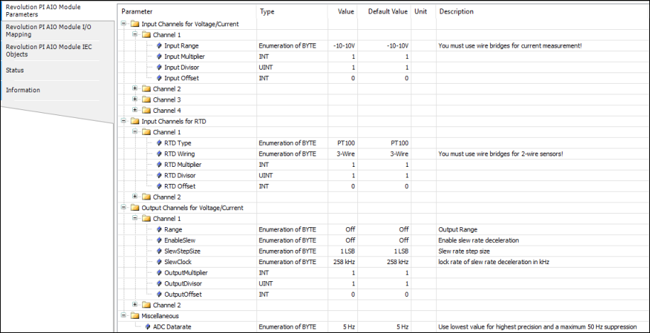
Configurable Values of the Analog Inputs of the RevPi AIO
Your RevPi AIO has four analog inputs. These inputs can be set as either voltage or current inputs. Here you can connect sensors, such as proximity or level sensors with analog inputs (typically 4 … 24 mA or 0 … 10 V).
For your configuration to work it is important that your devices are connected to the correct input pins.
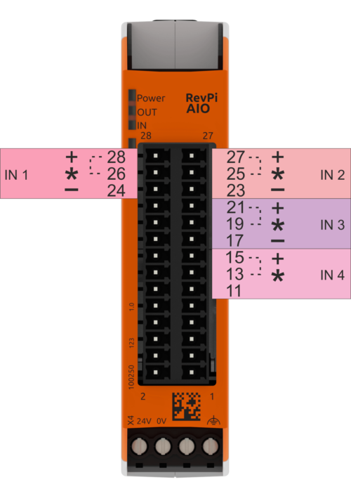
| Input 1 | |
| Pin | Application |
| 24 | - negative input for current or voltage measurement channel 1 |
| 26 | *a wire bridge must be installed for current measurements from here to pin 28 |
| 28 | + positive input for current or voltage measurement channel 1 |
| Input 2 | |
| Pin | Application |
| 23 | - negative input for current or voltage measurement channel 2 |
| 25 | *a wire bridge must be installed for current measurements from here to pin 27 |
| 27 | + positive input for current or voltage measurement channel 2 |
| Input 3 | |
| Pin | Application |
| 17 | - negative input for current or voltage measurement channel 3 |
| 19 | *a wire bridge must be installed for current measurements from here to pin 21 |
| 21 | + positive input for current or voltage measurement channel 3 |
| Input 4 | |
| Pin | Application |
| 11 | - negative input for current or voltage measurement channel 4 |
| 13 | *a wire bridge must be installed for current measurements from here to pin 15 |
| 15 | + positive input for current or voltage measurement channel 4 |
The detailed setting can be found in the following table:
| Variable | Values | Comment |
|---|---|---|
| Input1Range, Input2Range, Input3Range, Input4Range | Set the input range for voltage or current measurement here. The measuring method (current or voltage) as well as the range should match the output of the connected sensor. Typical values for industrial sensors are 0 ... 10 V or 4 ... 24 mA | |
| ADC_DataRate | Set the frequency here, which is used as data rate at the analog converter. The rate at which the values in the process image are updated is approximately 1/5 of this ADC data rate. This frequency applies to all four inputs. | |
| Scaling input 1-4: Input1Multiplier Input1Divisor Input1Offset | Here you can set a scaling for every output channel. It is determined by the three configuration values and calculated from the original value (available in mV or µA) according to the following formula: Y = X*Multiplier/Divisor + Offset |
Note that you can only output either current or voltage on one channel. For a current measurement a jumper, which you have to attach externally yourself, connects a load resistor ("shunt") between the inputs for the voltage measurement. The modification of the ranges in PiCtory changes practically nothing in the measuring electronics, but is only used for the conversion to mV or µA and the monitoring of the threshold values. Only for the 0 … 5 V range the input sensitivity of the measuring amplifier is increased, so double accuracy is achieved in this range (maximum deviation in this range is 5 mV).
The scaling can subsequently be used for conversion in other units or for a subsequent calibration of a sensor. A 32-bit integer arithmetic is used for calculations in the RevPi AIO module. The results are then however stored as 16-bit values in the process image. Should the result Y exceed the limits of a 16 bit signed value, then the fault will be recognised and the value limited. The output values are always in the units mV or µA.
Example
A proximity sensor outputs the voltage 0 to 10 V in the range between 30 and 300 millimeters. To have the distance in mm in the process image, you must select the parameters as follows:
Multiplier = 270, Divisor = 10000, Offset = 30
If the sensor works with 4… 20 mA instead, the values , must be defined by you as follows:
Multiplier = 270, Divisor = 16000, Offset = -38
ADC_DataRate
The module uses a so-called delta-sigma converter of the type ADS 1248. This converter has an adjustable data rate, which is closely related to the frequency curve of the digital filter contained in such a converter. Detailed diagrams of the frequency responses obtained for each setting are given in the ADS 1248 data sheet. Important for your measurements is here that low-frequency interfering signals, like for example a 50 Hz humming, can only be effectively suppressed at settings from 5 to 20 Hz. You will get the highest measurement accuracy with these settings. However, this also reduces the update rate of the data values in the process image. The context is as follows:
| ADC_Data rate | Update rate in the PA |
|---|---|
| 5 Hz | 1 Hz |
| 10 Hz | 2 Hz |
| 20 Hz | 4 Hz |
| 40 Hz | 8 Hz |
| 80 Hz | 10 Hz |
| 160 Hz | 25 Hz |
| 320 Hz | max. 50 Hz |
| 640 Hz | max. 125 Hz |
Note that the table values for the 320 Hz and 640 Hz settings are maximum values only. The actual update rate achieved can be significantly lower in this area due to the load on the PiBridge. The load depends on your configuration and therefore the respective update rate for these ADC_DataRates can only be determined experimentally on your system and with your configuration. In general, these settings are therefore not recommended.
If an error occurs, you will receive error messages in the AI_Status_Ch1-4 channel on the AIO Module I/O Mapping tab. The values have the following meanings:
| Bit Position | Status Message |
|---|---|
| Bit 0 (LSB) | 0 = value is higher than the lower limit of the configured range1 = value is at least 20 mV or 20 µA lower than the lower limit of the configured range |
| Bit 1 | 0 = value is lower than the upper limit of the configured range1 = value is at least 20 mV or 20 µA higher than the upper limit of the configured range |
In the field InputValue_1-4 you now see the actual value of the input. If you use the input as a voltage input, the value is given in mV. If you use the input as a current input, the value is given in µA. In the fields InputValue_1-4 you can define symbolic names for the four analog input values.
RTD Channels for Temperature Measurements
CODESYS helps you to configure your RevPi AIO.
▷ Double-click on RevPi AIO in the CODESYS device tree.
▷ Navigate to the first tab Module Parameters.
▷ Click on the corresponding Value cell to set the values.
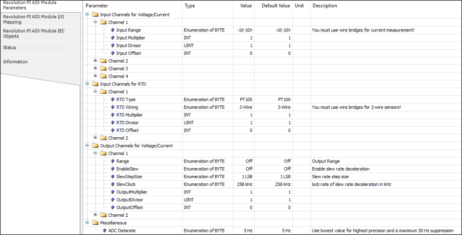
Configurable Values of the RTD Channels
Your RevPi AIO has two RTD channels. You can use it to determine the temperature of connected Pt100 and Pt1000 sensors.
For your configuration to work it is important that your devices are connected to the correct input pins.

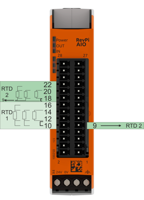
Note that the RevPi AIO module is used for a 2-wire sensor that uses the three-wire measurement system. Therefore, you have to simulate the missing third wire with a jumper between pins 10 and 12 and 9 and 18 respectively.
The detailed setting can be found in the following table:
| Variable | Values | Comment |
|---|---|---|
| RTD1Type, RTD2Type | Pt100 Pt1000 | Set here which type of measuring sensor you are using. |
| RTD1Wiring, RTD2Wiring | 2-Wire 3-Wire 4-Wire | Select here the measurement process that is suitable for your temperature sensor. |
| **RTD 1 scaling **RTD1Multiplier RTD1Divisor RTD1Offset **RTD 2 scaling **RTD2Multiplier RTD2Divisor RTD2Offset | 16 Bit signed Multiplier 16 Bit unsigned Divisor 16 Bit signed Offset | Set here the scaling for the RTD channels. This is determined by the three configuration values and calculated from the original value (which is available in 1/10 °C) using the following formula: Y = Multiplier/Divisor*X + Offset |
The scaling can be used for conversion to other units or for subsequent calibration of a temperature sensor. A 32-bit integer arithmetic is used for calculations in the RevPi AIO module. The results are then however stored as 16-bit values in the process image. Should the result Y exceed the limits of a 16-bit signed value, the fault will be recognised and the value limited.
Example:
To have the temperature in °C without decimal places in the process image, the setting must look like this:
Multiplier = 1, Divisor = 10, Offset = 0
To have the temperature in °F in the process image, the parameter have to be set like this:
Multiplier = 18, Divisor = 100, Offset = 32
For process data in °Kelvin you need these values:
Multiplier = 1, Divisor = 10, Offset = 273
Should an error occur, you will receive error message in the input values of the channels RTD_Status_Ch1 and RTD_Status_Ch2 located in tab AIO Module I/O Mapping. The values have the following meanings:
| Bit Position | Function | Comment |
|---|---|---|
| Bit 0 (LSB) | 0 = temperature is higher than -200 °C, 1 = the recorded temperature is lower than -200 °C (e.g. short circuit in sensor or cable) | Should the recorded temperature be outside the range, the respective limit will be issued (-200.0 °C or 850.0 °C) and the respective status bit will additionally be set. |
| Bit 1 | 0 = temperature is lower than 850 °C, 1 = the recorded temperature is higher than 850°C (e.g. no sensor connected or cable breakage). |
In the fields RTDValue_1 and RTDValue_2 you can define symbolic names for the 4 analog input values.
Configuring RevPi MIO
CODESYS helps you to configure your RevPi MIO.
▷ Double-click on RevPi MIO in the CODESYS device tree.
▷ Navigate to the first tab Module Parameters.
▷ Click on the corresponding Value cell to set the values.
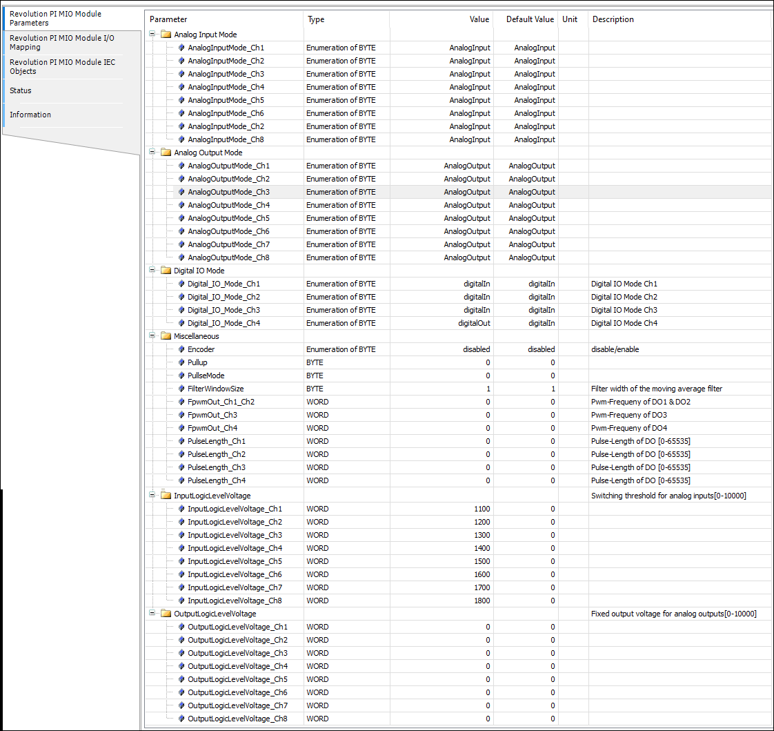
Configuring Digital Inputs and Outputs
The RevPi MIO has a GPIO interface with four connections, which you can use as an option in various operating modes:
- PWM input
- PWM output
- Pulse measurements
- Pulse output
- GPO 24 V level output
- GPI 24 V
The digital inputs and outputs use the same ground as the analog inputs and outputs. For this reason you should use one of the system ground connections on the 28-pin connector strip. If you don't use this ground, it's possible that your values will be distorted. If the voltage between the system ground and the ground of the digital inputs and outputs is too high, the protective diode can also be destroyed.
List of the Setting Values for the Digital Inputs and Outputs
| Variable | Values | Function |
|---|---|---|
| DigitalInput_1-5 | 0: low 1: high | The value indicates which level is present at the input. |
| Dutycycle_Pulselength_1-4 | 0 … 65535 | This value indicates the measured duty cycle or the measured pulse length, depending on which mode is set. |
| Fpwm/PulseCount_1-4 | 0 … 65535 | This value indicates the measured frequency or registered pulses, depending on which mode is set. |
| DigitalOutput_1-4 | 0: low 1: high | Here you can set the individual digital outputs to high or low. |
| PWM Dutycycle_1-4 | 0 … 1000 | You can set the duty cycle* for the individual digital outputs here. *The duty cycle specifies the ratio of the pulse duration to the period duration for a periodic sequence of pulses. |
| Encoder Mode | 0 = No encoder 1 = Encoder on GPIO3& 4 | If you set the value 1 here, you can use GPIO3 and GPIO4 as a quad encoder input. GPIO1 and GPIO2 can continue to be used as an output with all modes or as an input (no PWM, no pulse). |
| IO_Mode_1-4 | 0 = Input Connection is used as digital output. 1 = PulseInput Connection is used as digital input for pulse measurement. 2 = Pwm-Input Connection is used as digital input for PWM measurement. 3 = Output Connection is used as digital output. 4 = Output-Pulse Connection is used as digital output to deliver pulses. 5 = Output-Pwm Connection is used as digital output for pulse width modulation. | Here you can define the operating mode for the respective digital input or output. |
| PulseMode | 0 = Single 1 = Retrigger | Here you can activate the retrigger mode. |
| FPWMOUT_12, 3,4 | 0 … 65535 | 12= PWM frequency for digital outputs 1 and 2. These two connections always share the same PWM frequency. Connections 3 and 4 can be configured separately. |
| PulseLength_1-4 | 0 … 65535 | Pulse length on the respective digital output. |
Configuring Analog Inputs
Your RevPi MIO has eight analog outputs. These inputs can be used as a voltage input. Here you can connect sensors such as proximity or level sensors with analog outputs. The maximum common mode voltage per input may be between 0 and 10 V.
For your configuration to work it is important that your devices are connected to the correct input pins.
| Variable | Values | Comment |
|---|---|---|
| AnalogInputMode 1- 8 | Analog input: Connection is used for voltage measurement. LogicLevelInput: Connection is used for level detection. | Here you can define whether you wish to use the respective connection for level detection or for voltage measurement. |
| AnalogInputLogicLevel_1-8 | 0: Switching threshold has not been exceeded. 1: Switching threshold has been exceeded. | This value indicates whether the switching threshold has been exceeded. |
| Analog Input 1-8 | Logic 0-10 000 | Here you will see which input voltage is present at the respective analog input. The value is output in mV. |
| InputLogicLevelVoltage_1-8 | 0 … 10 000 | Here you can define the switching thresholds for the analog inputs. |
| FilterWindowSize | 1 … 255 | Filter width of the moving average filter. |
Configuring Analog Outputs
In the following example we will configure the first analog output to use to output voltage. You need this mode in order to use actuators such as setting elements or final control elements for controllers for example. To do this you will need to set the following configuration parameter:
Using Analog Output to Output Voltage
- AnalogOuputMode1 = AnalogOutput
- Analog Output 1 = Set a fixed output voltage here. The value must be between 0 and 10 000 and is stated in mV.
If you need more digital outputs, you can convert one of the analog outputs so that it behaves like a digital output. To do this you will need to set the following configuration parameter:
Using Analog Output as Digital Output
- AnalogOutputMode1 = LogicLevelOutput
- OutputLogicLevelVoltage 1 = Set a fixed output voltage here. The value must be between 0 and 10 000 and is stated in mV.
This is a summary of all the setting values for the analog outputs.
| Variable | Values | Function |
|---|---|---|
| AnalogOutputMode_1-8 | AnalogOutput: You can use the connection as analog output. LogicLevelOutput: You can use the connection as a digital output. | Set the function mode for the analog output here. |
| AnalogOutput 1-8 | 0 … 10 000 | Set the voltage that the respective analog output should deliver in mV here. |
| OutputLogicLevelVoltage 1-8 | 0 … 10 000 | Set a fixed voltage in mV here which the respective analog output should output. If a value not equal to 0 is entered for AnalogOutput_*, this voltage is output at the output. |
| AnalogOutputLogicLevel_1 | 0: low 1: high | If you are using the output as a digital output (function mode = LogicLevelOutput), here you can set the individual digital outputs to high or low. |
Configuring RevPi Gateways
CODESYS helps you to configure your RevPi Gateway.
▷ Double-click on RevPi Gateway in the CODESYS device tree.
▷ Click on the first tab Revolution PI Extension Bus I/O Mapping to configure the module.

The ModuleState byte has the following assignments:
| Value | Status |
|---|---|
| 0x00 | Physically offline |
| 0x01 | Physically connected but no communication |
| 0x02 | Standy/Ready (PreOp) |
| 0x03 | Cyclic data exchange active (Op) |
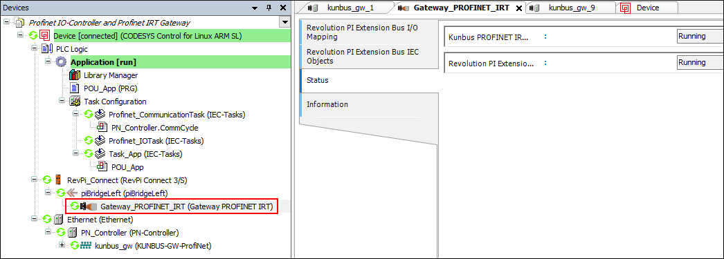
CODESYS returns No driver found status for the RevPi Gateway when the Gateway ModuleState is offline:

If the Gateway is in PreOp and Op status or is physically connected, the gateway icon in the CODESYS device tree is green:
Configuring RevPi Con CAN
Configuring CANopen Master
Prerequisites
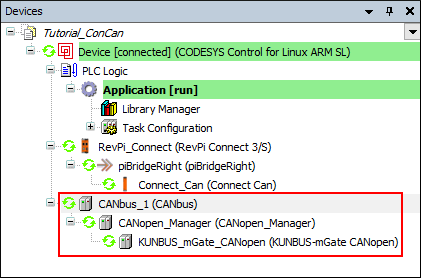
✓ A project is created using a RevPi Connect base module and a RevPi Con CAN expansion module at the piBridgeRight interface.
▷ Right-click on the root device.
▷ Click on Add Device.
▷ Select CANbus from the Fieldbuses.
▷ Click on Add.
▷ Right-click on the CANbus device.
▷ Click on Add Device.
▷ Select CANopen_Manager from the Fieldbuses.
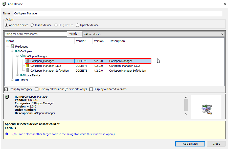
▷ Click on Add Device.
▷ Right-click on your project in the project tree.
▷ Click on Add Object.
▷ Insert the following objects: Task Configuration and POU.
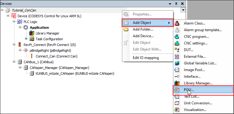
▷ Add the call POU to the task configuration.

▷ Download the project to the RevPi device.
▷ Log in via the Login icon in the menu bar.
❯❯ The CANopen master is in operation.
Insert KUNBUS CANopen mGate
▷ Right-click on the CANopen_Manager in the device tree.
▷ Click on Add Device.
▷ Select KUNBUS-mGate CANopen.
▷ Click on Add Device.
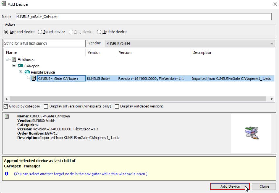
▷ Set the node ID and the bit rate of the gateway on the rotary coding switches of the device.
▷ Download the project to the RevPi device.
▷ Log in via the Login icon in the menu bar.
❯❯ The gateway is recognized by the master.
CODESYS Control for Linux ARM loads the file rts_set_baud.sh from /etc/codesyscontrol/CODESYSControl.cfgby default in order to be able to control the CAN bus interface from CODESYS.
[CmpSocketCanDrv]
ScriptPath=/opt/codesys/scripts/
ScriptName=rts_set_baud.sh
The default baud rate for the CAN interface can be changed in the file /opt/codesys/scripts/rts_set_baud.sh.
The rts_set_baud.sh script contains the following content by default:
#!/bin/sh
```BITRATE=`expr $2 \* 1000````
ip link set $1 down
ip link set $1 type can bitrate $BITRATE
ip link set $1 up
▷ Activate RevPi Con CAN either on the Config tab in PiCtory by activating Support RevPi Con Can device or using the following command:
sudo revpi-config enable revpi-con-can
▷ Download the CODESYS project.
▷ Important: Reboot the system or do a hard reset.
❯❯ The RevPi Con CAN module can now be used with CODESYS.
Configuring CANopen Slave
The CANopen slave is configured in the same way as the CANopen master.
The CANopen slave only needs to be configured for the slave function when setting the baud rate and activating the Con CAN module.
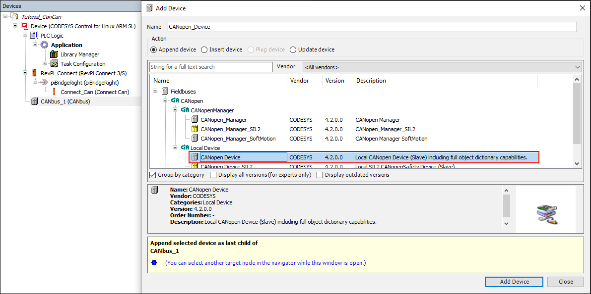
You can also take a look at the RevPi Con CAN example on this topic.
Configuring RevPi Virtual Device
The RevPi Virtual Device can be used to exchange data between CODESYS and other external applications such as Node-RED. The space provided for this purpose in the RevPi process image is used for this via a virtual interface.
Here we show you how to configure a RevPi Virtual Device in CODESYS.
Prerequisites
✓ A project with a RevPi device is created.
▷ Right-click on the device interface piBridgeVirtual in the project tree.
▷ Click on Add Device.
▷ Select RevPi_Virtual.
▷ Click on Add Device.
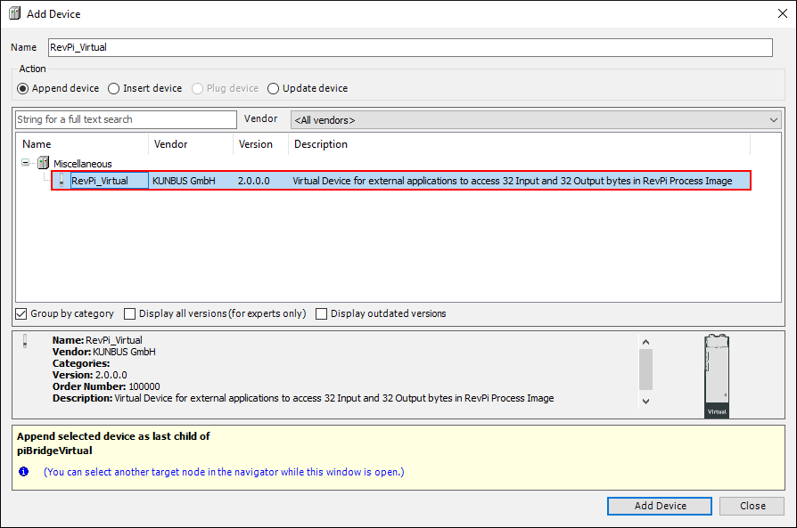
This device provides 32 bytes each of input and output memory in the RevPi process image for virtual access.
▷ Double-click on RevPi_Virtual to open the tab for the mapping.
▷ Enter a variable name for the 32-byte array of input and output.

▷ Write the code for your desired CODESYS project using the virtual device variables created in the previous step.
▷ Download the program.
❯❯ RevPi Virtual is now in operation.
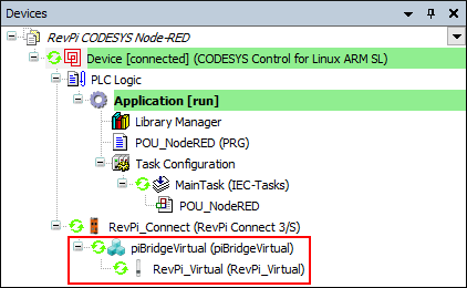
▷ Open PiCtory. In the following example, a RevPi Connect and a RevPi Virtual Device are displayed. This PiCtory configuration is created automatically each time CODESYS is started. It is only used as Read Only in PiCtory, as the config.rsc file is executed again after each restart of CODESYS. The variables of the virtual device can be seen in the figure below as Input_11_1 etc.
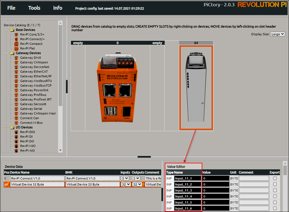
▷ Activate the Export fields for the variables that are used in the RevPi Virtual Device.
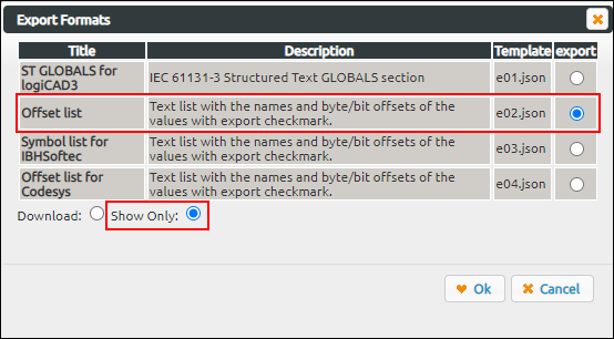
▷ Click on File/Export.
▷ Select Offset list, Show Only and confirm with Ok.
The offsets that refer to the RevPi Virtual Device in the process image are now listed.
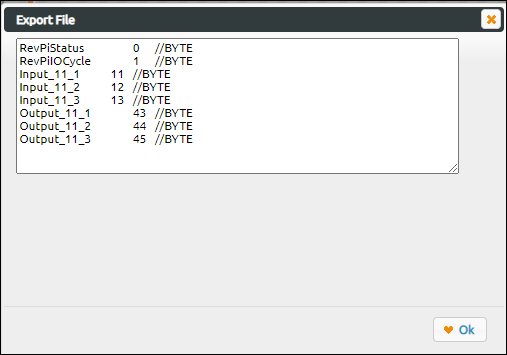
These variables can be accessed with external applications with the corresponding name or offset in the RevPi process image.
Example: With piTest you can read the 32 bytes of the virtual inputs (Input_11_1 to Input_11_32) from base offset 11 using the command piTest -r 11,32 .
Note: The outputs of the RevPi Virtual Device in CODESYS are written to the virtual inputs (Input_11_1 to Input_11_32) of the RevPi process image. External applications can write to virtual outputs (Output_1 to Output_32). These are then available as inputs of the RevPi Virtual Device in CODESYS.
CODESYS Tutorials
In the tutorials section you can find instructions for various application examples on how to use the RevPi devices together with CODESYS.